Model-based assist feature placement using inverse imaging approach

a technology of model-based assist and feature placement, applied in the field of electronic design automation, can solve the problems of difficult management, preventing designers from being able to achieve the best device performance, and missing or sub-optimal placement and/or dimensioning of assist features

Active Publication Date: 2011-08-30
SYNOPSYS INC
View PDF4 Cites 6 Cited by
  • Summary
  • Abstract
  • Description
  • Claims
  • Application Information

AI Technical Summary

Benefits of technology

[0008]During operation, the system can determine a spatial sampling frequency to sample the target mask layout, wherein sampling the target mask layout at the spatial sampling frequency prevents spatial aliasing in the gradient of the cost function. Next, the system can generate an anti-aliased grayscale image by sampling the target mask layout at the spatial sampling frequency. The system can then compute the inverse mask field by, iteratively, using the gradient of the cost function to modify the grayscale image, and updating the gradient of the cost function based at least on the modified grayscale image. Once the iterative process terminates, the system can identify locations for placing assist features based at least on the computed inverse mask field.

Problems solved by technology

Unfortunately, at smaller technology nodes, rule-based approaches can result in missed or sub-optimal placement and / or dimensioning of assist features.
Additionally, large and complex layouts can require a large number of design rules, which can be very difficult to manage.
Moreover, design rules can be overly restrictive which can prevent designers from being able to achieve the best device performance.
Unfortunately, the conventional LT-based approaches suffer from a number of shortcomings.
Specifically, conventional ILT-based techniques usually cannot accurately represent all patterns in the mask layout, require unreasonably large amounts of computational time and resources, and result in asymmetric assist feature placements.

Method used


Image

  • Model-based assist feature placement using inverse imaging approach
  • Model-based assist feature placement using inverse imaging approach
  • Model-based assist feature placement using inverse imaging approach

Examples


Embodiment Construction

[0020]The following description is presented to enable any person skilled in the art to make and use the invention, and is provided in the context of a particular application and its requirements. Various modifications to the disclosed embodiments will be readily apparent to those skilled in the art, and the general principles defined herein may be applied to other embodiments and applications without departing from the spirit and scope of the present invention. Thus, the present invention is not limited to the embodiments shown, but is to be accorded the widest scope consistent with the principles and features disclosed herein.

Integrated Circuit (IC) Design Flow

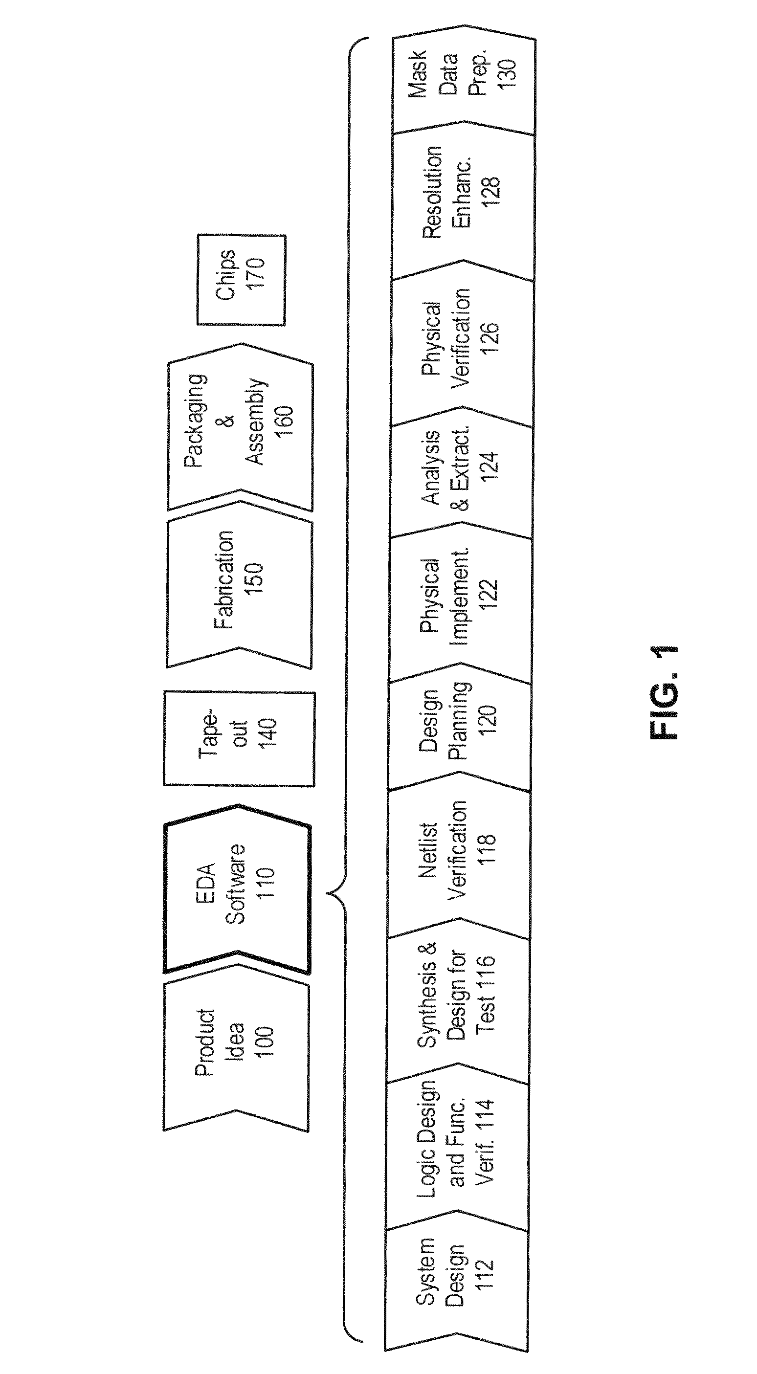
[0021]FIG. 1 illustrates various stages in the design and fabrication of an integrated circuit in accordance with an embodiment of the present invention.

[0022]The process can start with a product idea (step 100) which can be realized using an integrated circuit that is designed using an EDA process (step 110). After the inte...


PUM


Abstract

Some embodiments provide techniques and systems to identify locations in a target mask layout for placing assist features. During operation, an embodiment can determine a spatial sampling frequency to sample the target mask layout, wherein sampling the target mask layout at the spatial sampling frequency prevents spatial aliasing in a gradient of a cost function which is used for computing an inverse mask field. Next, the system can generate a grayscale image by sampling the target mask layout at the spatial sampling frequency. The system can then compute the inverse mask field by iteratively modifying the grayscale image. The system can use the gradient of the cost function to guide the iterative modification process. Next, the system can filter the inverse mask field using a morphological operator, and use the filtered inverse mask field to identify assist feature locations in the target mask layout.

Description

FIELD[0001]This disclosure generally relates to electronic design automation. More specifically, the disclosure relates to methods and apparatuses for model-based assist feature placement using an inverse imaging approach.BACKGROUNDRelated Art[0002]Rapid advances in computing technology have made it possible to perform trillions of computational operations each second on data sets that are sometimes as large as trillions of bytes. These advances can be attributed to the dramatic improvements in semiconductor design and manufacturing technologies which have made it possible to integrate tens of millions of devices onto a single chip.[0003]One such technology involves placing assist features in a mask layout. Note that assist features can be printing (e.g., super-resolution assist features) or non-printing (e.g., sub-resolution assist features). In either case, assist features are meant to improve the through process window of the patterns on the mask layout that are intended to be pr...

Claims


Application Information

Patent Timeline
Patent Type & Authority Patents(United States)
IPC IPC(8): G06F17/50
CPCG06F17/5081G06F30/398
Inventor POONAWALA, AMYN A.PAINTER, BENJAMIN D.BARNES, LEVI D.
Owner SYNOPSYS INC
Why Eureka
Try Eureka