Lacrosse head

a head and lacrosse technology, applied in the field of lacrosse head, can solve the problems of limiting the configuration by which a player can play and still providing a player with a limited amount of options, and achieve the effect of high customization, simple and efficient, and high confidence and efficiency levels

Inactive Publication Date: 2011-09-13
WARRIOR SPORTS INC
View PDF12 Cites 22 Cited by
  • Summary
  • Abstract
  • Description
  • Claims
  • Application Information

AI Technical Summary

Benefits of technology

[0010]In a further embodiment, the cross member can define multiple first holes and multiple second holes. The first holes can be aligned along a first contour, while the second holes can be aligned along a second contour of the cross member. By attaching a lacrosse net to selected ones of the first holes and the second holes in a desired combination, a user can provide the lacrosse net with a desired pocket profile.
[0014]The lacrosse head of the present invention provides a simple and efficient construction that enables users to string the lacrosse head with the lacrosse net at the bottom, middle, top or any point in between, depending on the desired characteristics of the net or the pocket profile. This provides users with a highly customized pocket, and thus enables them to play at a much higher confidence and efficiency levels. Further, where the net attachment points are raised above the lower rail of the sidewall, a deeper NCAA Rule compliant pocket can be effectively formed, providing the player with better ball feel and hold. Finally, where the upper and lower rails are void of conventional string holes, or simply have a reduced number of conventional string holes, the strength of the sidewalls can be increased, as such conventional string holes can often weaken these structures.

Problems solved by technology

While this construction frequently provides the desired amount of ball retention, it limits the configurations by which a player can string a net to the head and achieve a particular catching or shooting feel.
While altering the location where the net is strung to the wall, this construction still provides somewhat limited options to a player because the net is confined to a single predetermined location dictated by the manufacturer's placement of the string holes.

Method used


Image

  • Lacrosse head
  • Lacrosse head
  • Lacrosse head

Examples


Embodiment Construction

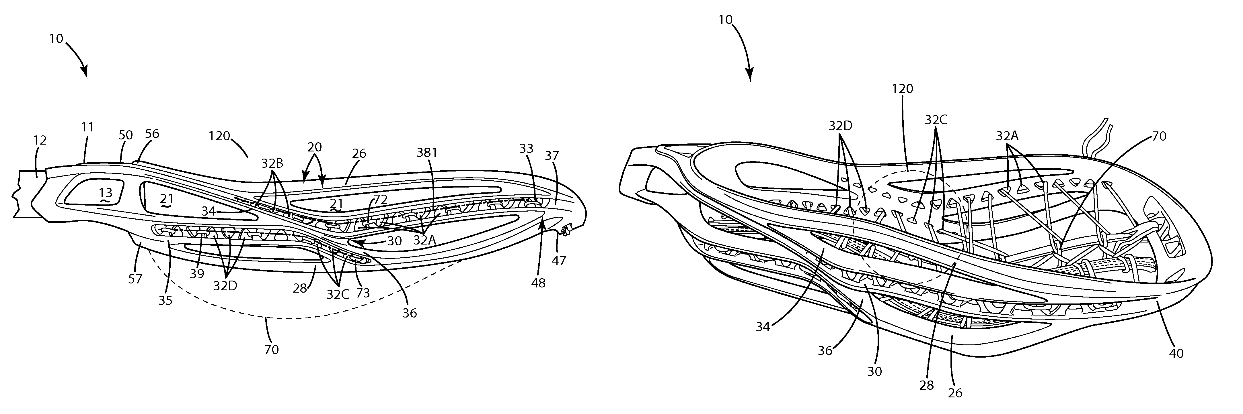
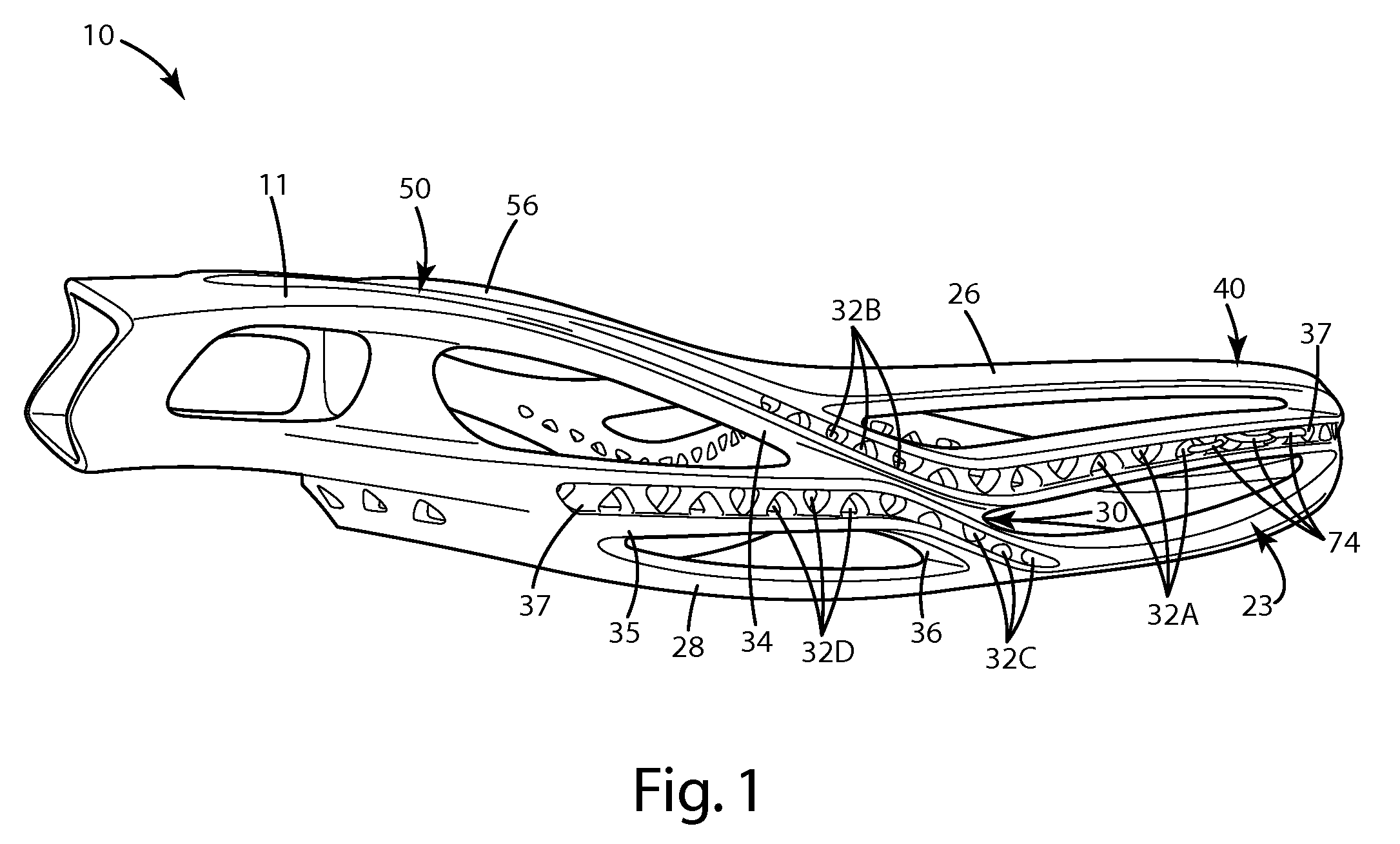
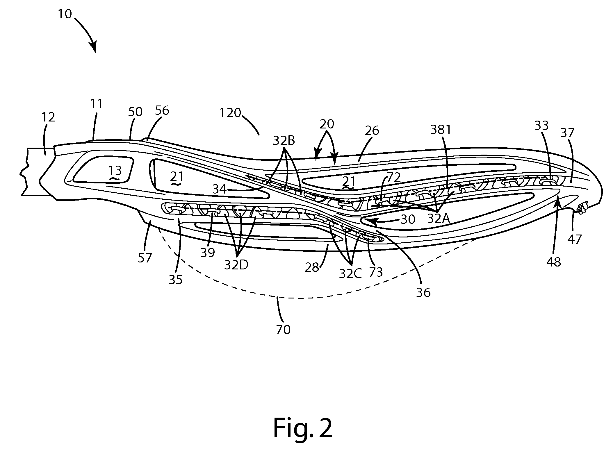
[0024]A current embodiment of the lacrosse head of the present invention is shown in FIGS. 1-5 and generally designated 10. The lacrosse head 10 includes a throat 11 adapted to connect to a lacrosse handle 12, a pair of opposing sidewalls 20 and a scoop 40 connecting the pair of opposing sidewalls 20 opposite the throat 11. Located at the lower end of the head, adjacent the throat 11, is a base 50 which includes a ball stop 52. The sidewalls 20 can sidewall be of an open frame construction, that is, they can define at least one non-string hole that is adapted to reduce the weight of the head, such as the frame hole 21. Each sidewall can also include an upper rail 26 and a lower rail 28 separated from one another by a distance. A cross member 30 can be joined with the upper rail and the lower rail. The cross member 30 can define multiple holes 32A-D that can both serve to reduce weight of the head and provide locations where attachment strings from a lacrosse net can be joined. Each ...


PUM


Abstract

A lacrosse head includes sidewalls having an open frame construction. The sidewalls include an upper rail and a lower rail, along with a cross member joined with the upper rail and the lower rail. The cross member defines multiple holes corresponding to multiple pocket configurations so that a user can attach a lacrosse net to selected ones of the holes and achieve a desired pocket profile. Optionally, at least one of the upper and lower rails can be void of any string holes. Further optionally, the cross member can branch into one or more secondary members that also define string holes to provide additional pocket profiles. Even further optionally, the holes defined by the cross member can be of polygonal shape.

Description

BACKGROUND OF THE INVENTION[0001]The present invention generally relates to a lacrosse head for attachment to a lacrosse handle, and more particularly to a lacrosse head including holes defined in the structure of the sidewalls of the head adapted to accommodate pocket strings.[0002]Conventional lacrosse heads typically include an open frame having a ball stop joined with the base, a pair of sidewalls that diverge from the ball stop, and a scoop that connects the sidewalls, opposite the ball stop. The sidewalls generally include a lower portion, such as a lower rim, that defines multiple circular or elliptical string holes. A lacrosse net is strung to the lower rim via the string holes, around the back side of the frame, leaving the opposing side of the frame open for catching or shooting a lacrosse ball.[0003]Many heads also are configured so that the netting hangs downward from the lowermost portion of the frame, having minimal to no contact with the sidewalls—other than where the...

Claims


Application Information

Patent Timeline
Patent Type & Authority Patents(United States)
IPC IPC(8): A63B59/02A63B65/12
CPCA63B59/02A63B49/002A63B49/007A63B59/0088A63B49/022A63B49/028A63B59/20A63B60/50A63B2102/14
Inventor LAMSON, KYLE L.PAQUETTE, ADAM D.
Owner WARRIOR SPORTS INC
Why Eureka
Try Eureka