Dual-rotor electric traction motor

Inactive Publication Date: 2008-12-16
RADEV VLADIMIR
View PDF7 Cites 79 Cited by
  • Summary
  • Abstract
  • Description
  • Claims
  • Application Information

AI Technical Summary

Benefits of technology

[0021]This invention provides a dual-rotor electric traction motor with relatively simple, reliable, and easily accessible means for conducting the electric current from the stationary terminals to

Problems solved by technology

In spite of the remarkable mechanical simplicity and efficiency of the drive systems for electric and hybrid-electric vehicles using dual-rotor motors, they have not achieved wide application, due to difficulties in two major areas in the construction of the dual-rotor traction motor itself.
These difficulties stem from the fact that the two major components of a dual-rotor motor—field and armature—are rotating parts.
The first major difficulty relates to the conduction of electric current from static terminals attached to the motor enclosure to the windings of the rotating outer rotor and to the windings of the rotating inner rotor of the dual-rotor motor.
However, the conduction of electric current from the outer router to the inner rotor is very

Method used


Image

  • Dual-rotor electric traction motor
  • Dual-rotor electric traction motor
  • Dual-rotor electric traction motor

Examples


Example

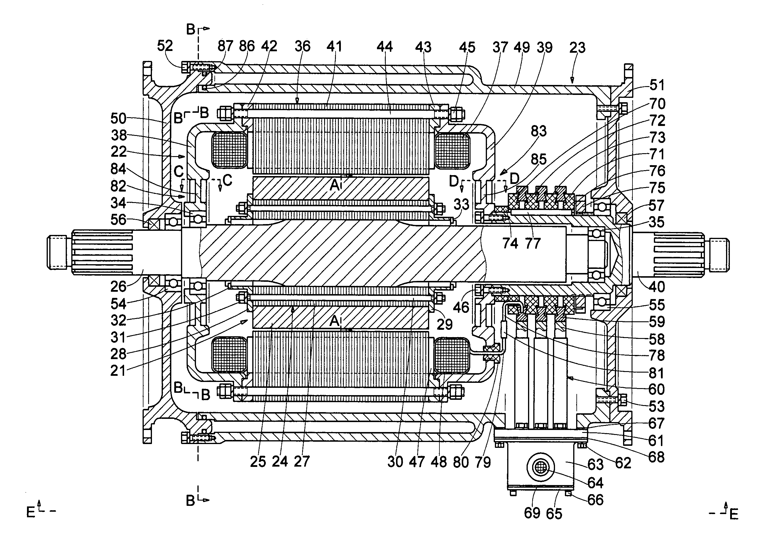
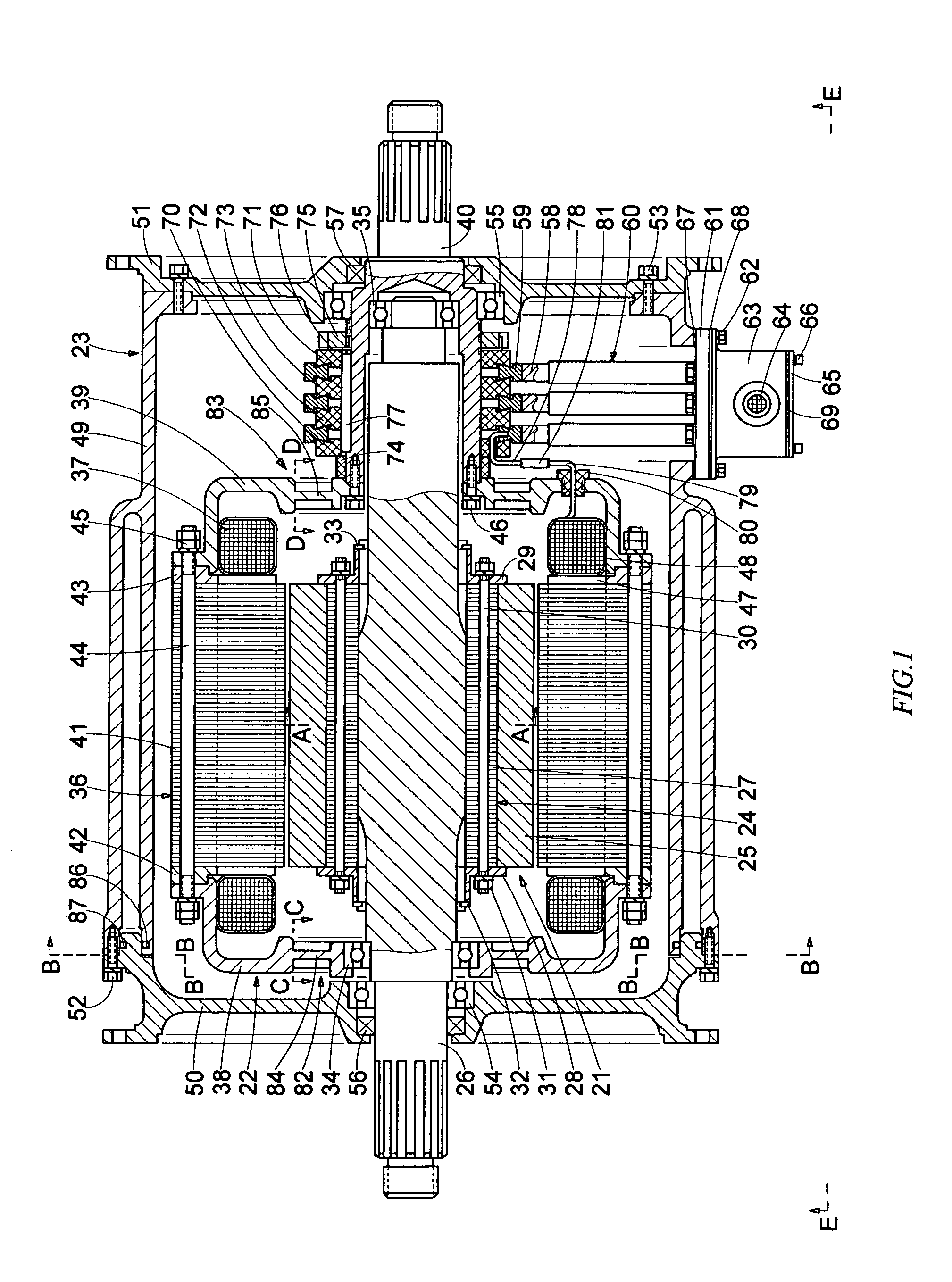
[0085]In this first embodiment, an external liquid-cooling system cools the motor enclosure 23. Usually, a motor liquid-cooling system includes a radiator and a fan for cooling the hot liquid coolant coming from the motor, a pump for circulating the coolant between the motor enclosure and radiator, and a plurality of connecting lines. Since such liquid-cooling systems are well known in the art, and for simplicity of drawings and description, the entire external cooling system is not shown, but only an arrangement of the motor enclosure for liquid cooling is illustrated and described.

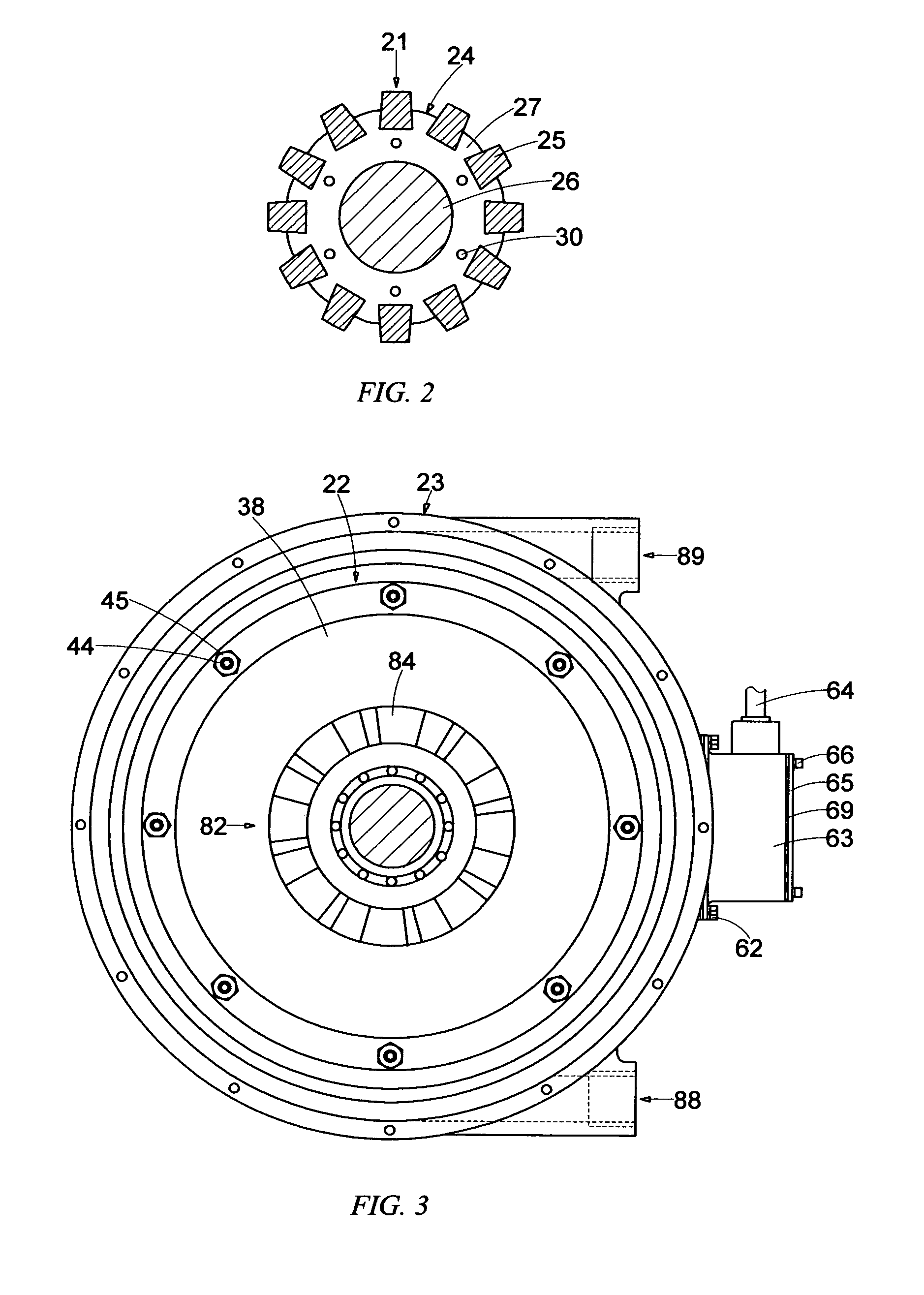
[0086]Referring to FIG. 1, FIG. 3, and FIG. 6, in this embodiment, a part of the central cylindrical enclosure 49 has a double wall forming a substantially cylindrical cavity, in which the liquid coolant can flow. The first motor enclosure side flange 50, closes this cylindrical cavity, and two O-rings 86, 87 seal between the cylindrical enclosure and the first motor enclosure side flange.

[0087]An inlet ...

Example

[0100]Referring now to FIG. 10, FIG. 11, and FIG. 12, which illustrate a third embodiment of a dual-rotor motor according to this invention, in addition to the two outer rotor axial fans 82, 83 of the first embodiment, an inseparable part of the armature core 36 is arranged as a peripheral axial fan 99 between the outer cylindrical surface of the armature core and the inner cylindrical surface of the motor enclosure. The sectional view in FIG. 11 has been rotated in the plane of the drawing 90° counter-clockwise for showing the motor in its natural position.

[0101]In this embodiment, eight blades 100 are evenly spread out upon the outer cylindrical surface of the armature core. The blades are made of eight radial extensions of each of eight lamellas 101 (101 / 1 to 101 / 8), which extensions are evenly spread out upon the cylindrical circumference of each lamella, starting from a circumference equal to the circumference of the lamellas 41 without radial extensions and extending to a cyli...

Example

[0104]Referring to FIG. 13, FIG. 14, and FIG. 15, which illustrate a fourth embodiment of this invention, a peripheral axial fan 102, having four long spiral blades 103, is integrated with the outer rotor core 36. The sectional view in FIG. 14 has been rotated in the plane of the drawing 90° counter-clockwise for showing the motor in its natural position. This peripheral axial fan 102 is arranged in the same way, uses the same means, and operates in the same way as the peripheral axial fan 99 described with the third embodiment (FIG. 10 to FIG. 12). The number of the blades 103 and their extension upon the length of the outer rotor core are the only differences between the third and the fourth illustrated embodiments in this specification. Therefore, this fourth embodiment is not further discussed. However, the specific number and length of the blades are the choice of the designer of the motor.


PUM


Abstract

An inner rotor (21) is arranged as a motor field, including permanent magnets (25) embedded in an inner rotor core (24) and an inner rotor shaft (26) coupled with the inner rotor core. An outer rotor (22) is arranged as a motor armature, including a hollow armature core (36), plurality of windings (37), two side flanges (38, 39), and an outer rotor shaft (40) coupled with one of the side flanges. The inner rotor is rotatably supported inside the outer rotor, and both rotors are rotatably supported inside a stationary motor enclosure (23). Electric current is conducted to the windings of the armature via brushes (58) and sliprings (59). The interaction between a revolving electromagnetic field of the outer rotor and the permanent magnetic field of the inner rotor propels both rotors to rotate in opposite directions. Two axial fans (82, 83) integrated with the outer rotor side flanges and two axial fans (95, 96) coupled with the inner rotor shaft work in series and produce continuous internal close-loop air circulation between both rotors and between the outer rotor and the motor enclosure, for improving the rate of heat transmission from the rotors to the motor enclosure. If the outer rotor is selectively immobilized, the two inner rotor axial fans produce the internal close-loop air circulation.

Description

FIELD OF THE INVENTION[0001]This invention relates generally to electric machines having two rotors and no stator, and more particularly to dual-rotor electric traction motors.BACKGROUND OF THE INVENTION[0002]The conventional electric machines—motors and generators—consist of a stationary component (the stator) and a rotating component (the rotor). One of these components is arranged to operate as the field and the other—as the armature of the electric machine. When a conventional electric motor is energized and electric current flows through its windings, the interaction between the electromagnetic forces of the field and armature propels the rotor to rotate and generates mechanical energy. When the rotor of a conventional electric generator rotates, driven by external mechanical forces, a magnetic field rotating in relation to the armature windings cuts through the armature windings and produces voltage at the output terminals of the generator.[0003]Dual-rotor electric motors, tho...

Claims


Application Information

Patent Timeline
IPC IPC(8): H02K16/02H02K9/00
CPCH02K1/32H02K9/06H02K16/005H02K9/10H02K9/14H02K1/22H02K5/20H02K9/19H02K5/203H02K5/207
Inventor RADEV, VLADIMIR
Owner RADEV VLADIMIR
Why Eureka
Try Eureka