

Power transfer system and method
a power transfer system and power technology, applied in the direction of charging stations, electric vehicle charging technology, transportation and packaging, etc., can solve the problems of difficult to achieve tolerability along curved tracks, affecting the stability of the power supply system, and requiring heavy anchoring of the stanchions
- Summary
- Abstract
- Description
- Claims
- Application Information
AI Technical Summary
Benefits of technology
Problems solved by technology
Method used
Image

Examples
Embodiment Construction
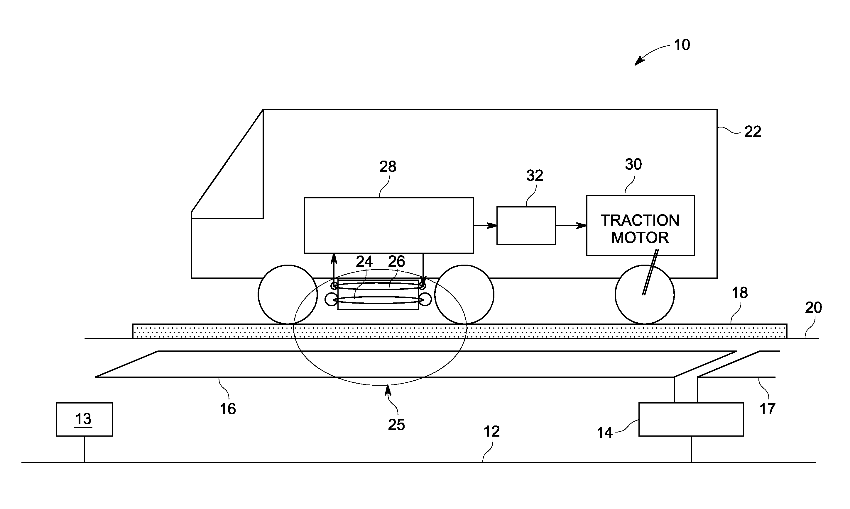
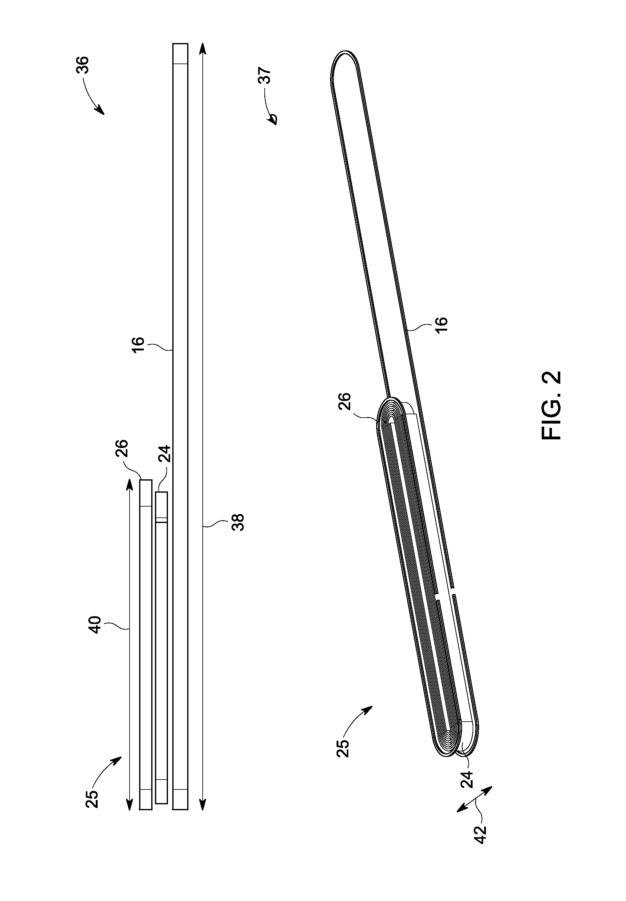
[0016]Embodiments of the invention relate to a power transfer system and an associated method. Particularly, a power transfer system for use with a mobile asset is provided for herein, and in which the power transfer may be contactless.
[0017]By contactless, it is meant that a power cord, wire, or other tangible electrical conduit is absent for at least a portion of a power transfer circuit. Unless otherwise indicated by context or explicit language, power, as used herein, refers to electrical power or electricity. A mobile asset can include any non-fixed item of equipment, and specifically includes at least self-propelled vehicles. Examples of such vehicles can include passenger vehicles, mass transit vehicles, locomotives, and industrial equipment (e.g., forklifts and loaders). Other examples can include mining equipment and semi-portable devices. Further, instances are contemplated where the asset itself is fixed, but the power source for the power transfer system is relatively mo...
PUM
| Property | Measurement | Unit |
|---|---|---|
| transmission voltages | aaaaa | aaaaa |
| resonance frequency | aaaaa | aaaaa |
| frequencies | aaaaa | aaaaa |
Abstract
Description
Claims
Application Information