Heart monitoring device and method

a heart monitoring and heart rate technology, applied in the field of medical devices, can solve the problems of increasing the risk of thromboembolic stroke in af patients, increasing the risk of thromboembolic stroke in patients, and all existing methods have various limitations, and achieves a more robust cardiac rhythm classification

Inactive Publication Date: 2011-09-13
BIOTRONIK SE & CO KG
View PDF21 Cites 26 Cited by
  • Summary
  • Abstract
  • Description
  • Claims
  • Application Information

AI Technical Summary

Benefits of technology

[0010]It is an objective of the invention to provide a device or a method or both that provides for more robust cardiac rhythm classification.

Problems solved by technology

On the other hand, structural or functional abnormalities of the cardiac electrical conduction system can lead to cardiac arrhythmias.
Moreover, it is well known that AF patients have significantly higher risk of thromboembolic stroke.
Nonetheless, all existing methods have various limitations.
However, the specificity for AF detection using these simple variability metrics is not sufficiently high, because many other types of cardiac rhythms (e.g., exercise, frequent extra-systoles, etc.) also show large variability of RR intervals.
However, these measures only reflect the global complexity of the RR intervals, whereas it is known that many types of cardiac rhythms have overlapping range of RR interval complexity, for example, AF vs. ventricular fibrillation (VF), sinus rhythm with depressed HRV (e.g., in HF patients) vs. stable sinus tachycardia, and so on.
However, by focusing on the beat-to-beat change of the RR intervals (or change of heart rate), these dRR Lorenz plots ignore the information pertaining to the raw RR intervals (or heart rate).

Method used


Image

  • Heart monitoring device and method
  • Heart monitoring device and method
  • Heart monitoring device and method

Examples


Embodiment Construction

[0053]The following description is of the best mode presently contemplated for carrying out the invention. This description is not to be taken in a limiting sense, but is made merely for the purpose of describing the general principles of the invention. The scope of the invention should be determined with reference to the claims.

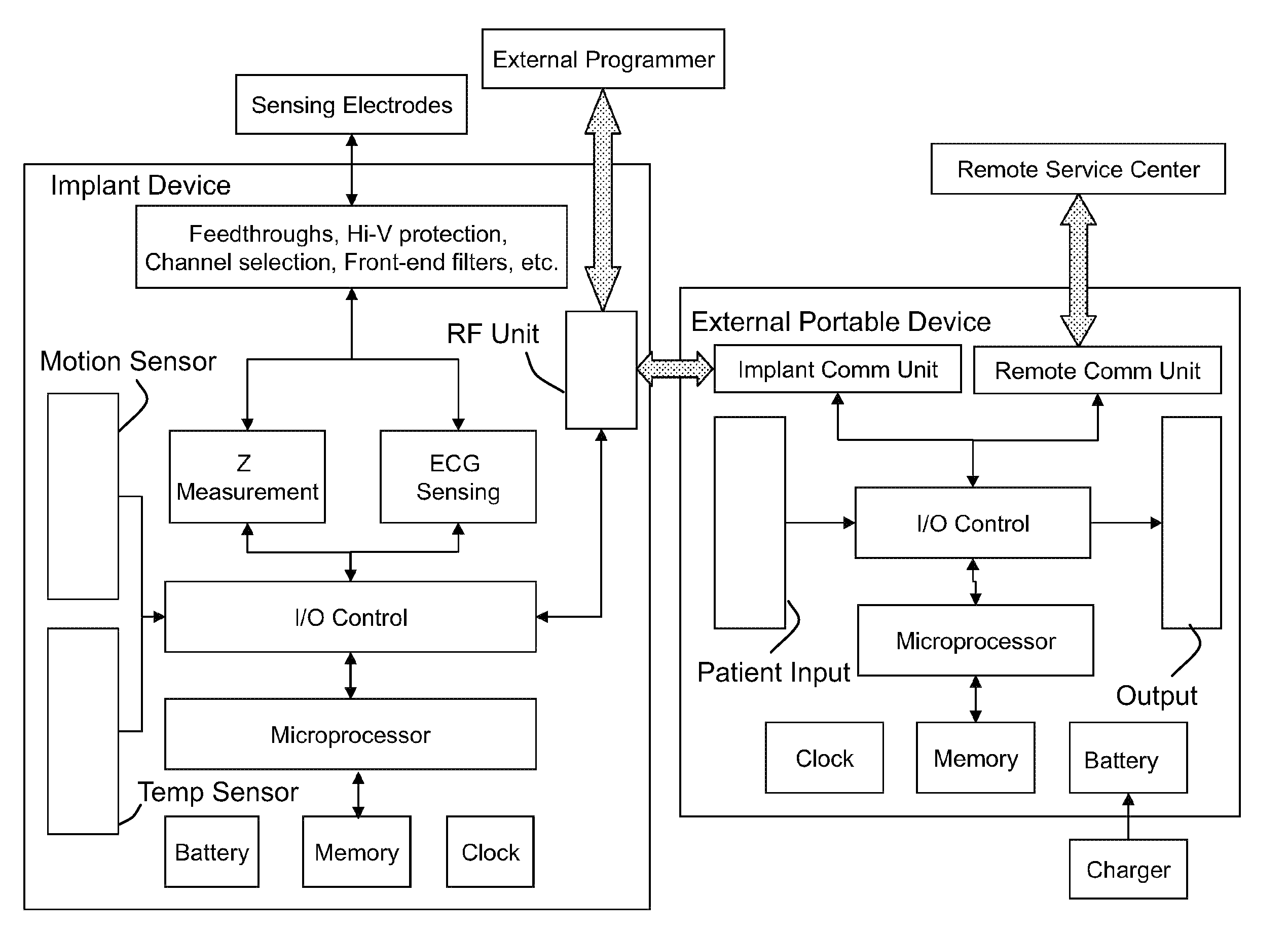
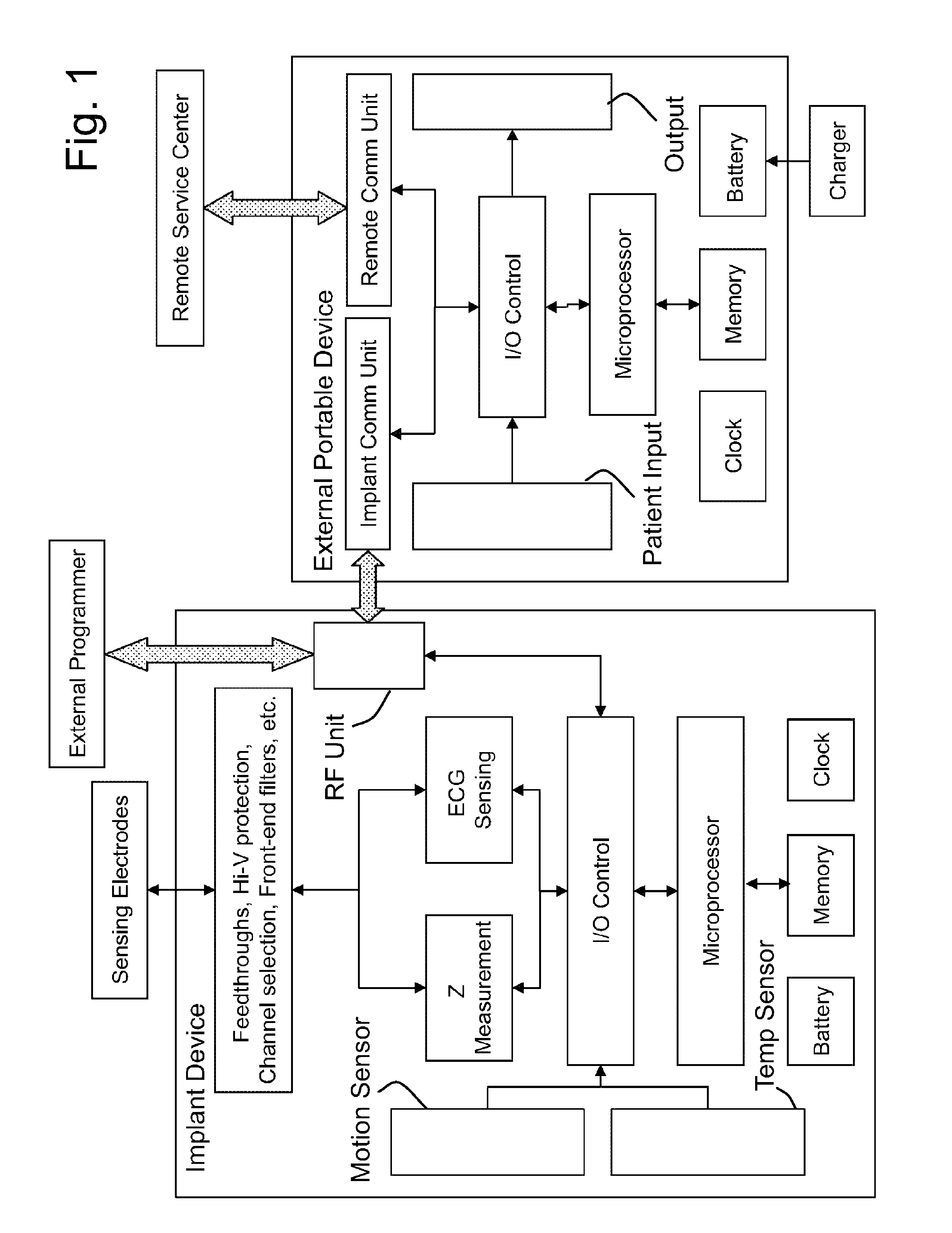
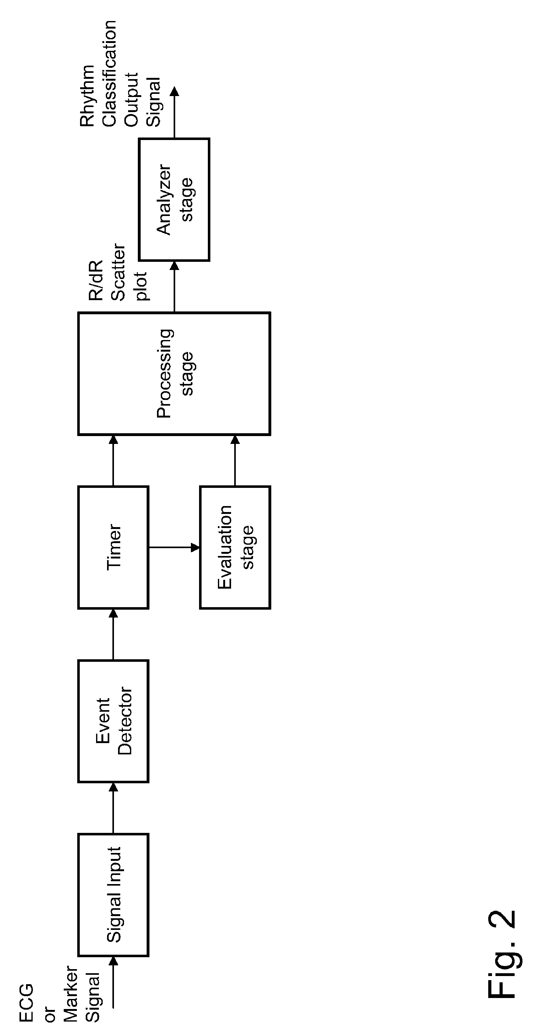
[0054]The present invention provides a method for automatic classification of cardiac rhythms by means of cardiac inter-beat interval analysis. The cardiac inter-beat intervals are preferably the RR intervals that are measured from the surface ECG signals (e.g., by Holter monitoring), or from the subcutaneous ECG signals (e.g., by implantable subcutaneous ECG monitoring), or from the intracardiac electrogram (e.g., by implantable pacemakers or defibrillators). Alternatively, the cardiac inter-beat intervals can also be obtained from other types of biosignals that are known to show the same rhythmic variation as the cardiac beats, including but not limited to...


PUM


Abstract

A heart monitor for processing input signals that represent periodically reoccurring events in a sequence of heart cycles. According to the invention graphical data representing a scatter plot of at least two dimensions, one dimension representing interval duration or its inverse and the other dimension representing change of duration or its inverse, respectively, are generated. The scatter plot comprises data points of which each data point represents heart interval duration or its inverse plotted against the change of duration with respect to a neighboring interval or the inverse of said change respectively.

Description

BACKGROUND OF THE INVENTION[0001]1. Field of the Invention[0002]The present invention generally relates to medical devices that measure cardiac inter-beat intervals, analyze the said cardiac inter-beat intervals, and classify the underlying cardiac rhythm based on the said cardiac inter-beat intervals. More particularly, the present invention relates to a method and apparatus for accurate detection of atrial fibrillation based on analysis of the cardiac inter-beat intervals.[0003]2. Description of the Related Art[0004]The variation of cardiac inter-beat (e.g., PP, RR) intervals results from both rhythmic activity of the heart electrical source and the dynamic properties of the cardiac conduction pathway, both of which are under autonomic control. In normal sinus rhythm, the RR intervals are known to fluctuate at various time scales, a phenomenon known as heart rate variability (HRV), which has been extensively investigated to probe the autonomic nervous activity. On the other hand, ...

Claims


Application Information

Patent Timeline
Patent Type & Authority Patents(United States)
IPC IPC(8): A61B5/04
CPCA61B5/02405A61B5/0452G06K9/0053G06K9/00557A61B5/7264A61N1/3702A61B5/349G06F2218/18G06F2218/10
Inventor LIAN, JIEMUESSIG, DIRK
Owner BIOTRONIK SE & CO KG
Why Eureka
Try Eureka