
Exhaust gas purification system for internal combustion engine

a technology of exhaust gas purification system and internal combustion engine, which is applied in the direction of mechanical equipment, machines/engines, electric control, etc., can solve the problems of fuel added through the fuel addition valve being likely to slip through fuel economy deterioration, and increase in fuel emitted to the exterior, so as to improve the recovery of exhaust gas purification performance and promote the chemical reaction for recovering the performance of the exhaust gas purification apparatus.

Inactive Publication Date: 2011-09-20
TOYOTA JIDOSHA KK
View PDF11 Cites 2 Cited by
  • Summary
  • Abstract
  • Description
  • Claims
  • Application Information

AI Technical Summary

Benefits of technology

[0006]The present invention has been made in view of the above described problem and has as an object to provide a technique that enables to recover the performance of an exhaust gas purification apparatus while suppressing slipping of fuel through the exhaust gas purification apparatus.
[0018]With the above feature, even in a case where the performance of the exhaust gas purification apparatus is to be recovered when the intake air quantity of the internal combustion engine is increasing, it is possible to supply a quantity of fuel equal to the target fuel supply quantity to the exhaust gas purification apparatus while suppressing slipping of fuel through the exhaust gas purification apparatus. Thus, according to the present invention, recovery of the performance of the exhaust gas purification apparatus can be achieved while suppressing slipping of fuel through the exhaust gas purification apparatus.
[0021]By setting the upper limit value of the fuel addition quantity as described above, better control of slipping of fuel through the exhaust gas purification apparatus can be achieved.
[0025]By correcting the sub fuel injection quantity in the above described manner, the chemical reaction for recovering the performance of the exhaust gas purification apparatus can be further promoted. Consequently, recovery of the performance of the exhaust gas purification apparatus can be further improved.

Problems solved by technology

If the flow rate of the exhaust gas is increasing when fuel is added into the exhaust gas through a fuel addition valve in order to recover the performance of an exhaust gas purification apparatus, the fuel added through the fuel addition valve is likely to slip through the exhaust gas purification apparatus.
Consequently, there is a possibility that the quantity of fuel emitted to the exterior increases and the fuel economy is deteriorated.

Method used


Image

  • Exhaust gas purification system for internal combustion engine
  • Exhaust gas purification system for internal combustion engine
  • Exhaust gas purification system for internal combustion engine

Examples


Embodiment Construction

[0030]In the following, a specific embodiment of the exhaust gas purification system for an internal combustion engine according to the present invention will be described with reference to the drawings.

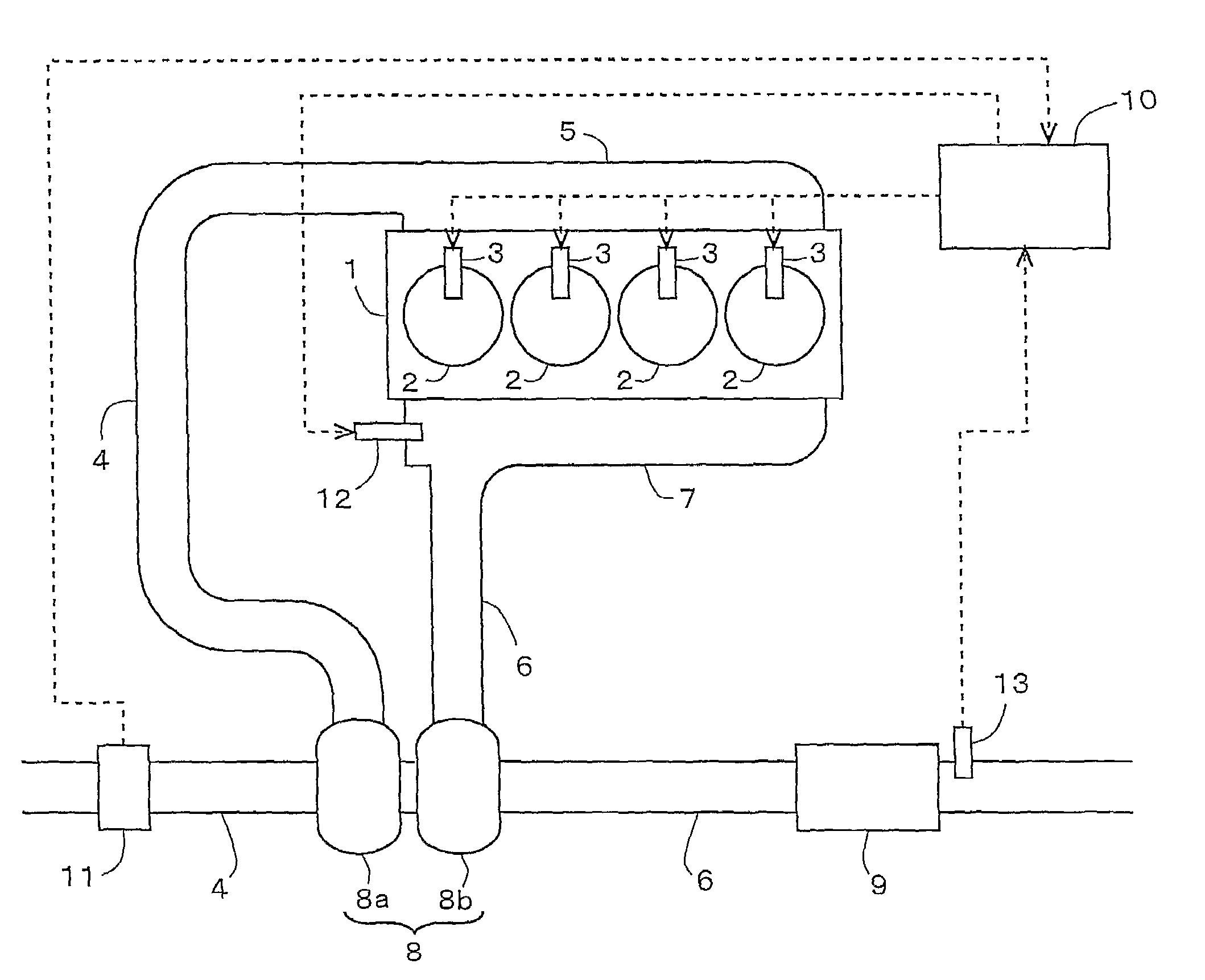
[0031]FIG. 1 is a diagram schematically showing the general structure of the internal combustion engine and its air-intake and exhaust systems according to an embodiment. The internal combustion engine 1 is a diesel engine having four cylinders 2 for driving a vehicle. Each cylinder 2 is provided with a fuel injection valve 3 that injects fuel directly into the cylinder 2.

[0032]To the internal combustion engine 1 is connected an intake manifold 5 and an exhaust manifold 7. One end of an intake passage 4 is connected to the intake manifold 5. One end of an exhaust passage 6 is connected to the exhaust manifold 7.

[0033]The intake passage 4 is provided with an air flow meter 11 and a compressor 8a of a turbocharger 8. The exhaust passage 6 is provided with a turbine 8b of the turbocharg...


PUM


Abstract

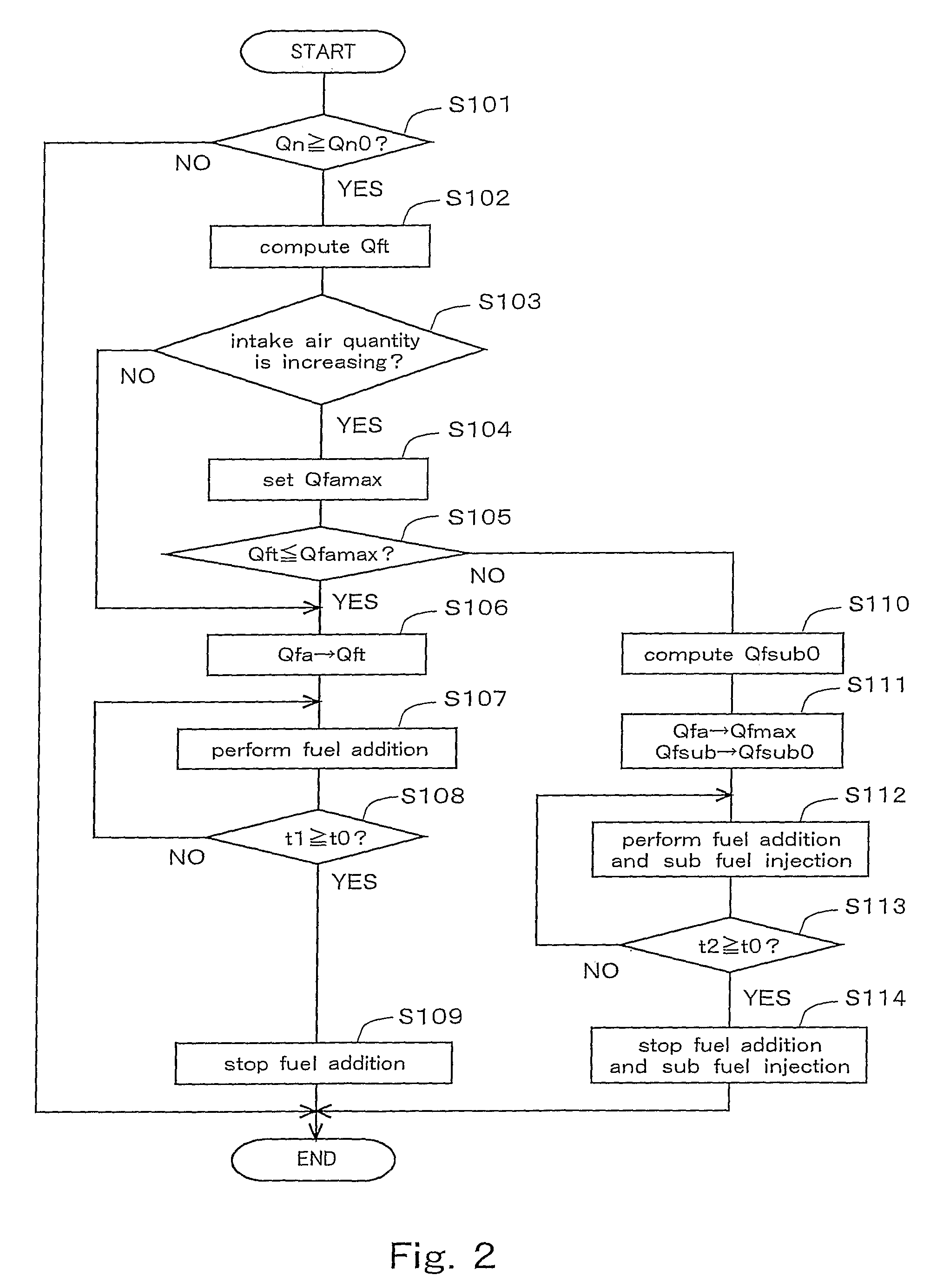
An object of the present invention is to recover the performance of an exhaust gas purification apparatus while suppressing slipping of fuel through the exhaust gas purification apparatus. When the performance of the exhaust gas purification apparatus is to be recovered at a time when the intake air quantity of the internal combustion engine is increasing (S101, S103), an upper limit value is set for the quantity of fuel added through a fuel addition valve provided in the exhaust passage (S104). If a target fuel supply quantity to be supplied to the exhaust gas purification apparatus is larger than the upper limit value (S105), a quantity of fuel quantity equal to the upper limit value is added through the fuel addition valve, and the shortfall of fuel supply is injected by sub fuel injection in the internal combustion engine (S110, S111, S112).

Description

[0001]This application is the national phase application under 35 U.S.C. §371 of PCT International Application No. PCT / JP2007 / 064720 filed on 20 Jul. 2007, which claims priority of Japanese Patent Application No. 2006-199069 filed on 21 Jul. 2008, the contents of which are incorporated herein by reference.TECHNICAL FIELD[0002]The present invention relates to an exhaust gas purification system for an internal combustion engine equipped with an exhaust gas purification apparatus provided in an exhaust passage of the internal combustion engine.PRIOR ART[0003]As exhaust gas purification systems for an internal combustion engine, systems equipped with an exhaust gas purification apparatus such as an NOx storage reduction catalyst (which will be simply referred to as an NOx catalyst, hereinafter) or a particulate filter on which an NOx catalyst is supported have been known. In the exhaust gas purification system for an internal combustion engine equipped with such an exhaust gas purificat...

Claims


Application Information

Patent Timeline
Patent Type & Authority Patents(United States)
IPC IPC(8): F01N3/00
CPCF01N3/0842F01N3/0871F01N3/2033F01N11/002F02D41/182F02D41/405F02D41/0275F01N2560/06F02D2200/0802Y02T10/26Y02T10/47Y02T10/12Y02T10/40
Inventor OBA, TAKAHIROTAKIMOTO, KATSUSHINEGAMI, AKIHIKO
Owner TOYOTA JIDOSHA KK
Learn More