Ink supply apparatus and printing apparatus

a technology of supply apparatus and printing head, applied in printing and other directions, can solve the problems of affecting affecting the supply of ink, and affecting the quality of printing, so as to reduce the waste of ink and recover the ejection performance of the print head

Inactive Publication Date: 2015-09-15
COPYER
View PDF30 Cites 1 Cited by
  • Summary
  • Abstract
  • Description
  • Claims
  • Application Information

AI Technical Summary

Benefits of technology

[0006]An object of the present invention is to provide a printing apparatus that enables a reduction in waste ink resulting from a recovery operation for removing bubbles in channels in order to recover the ejection performance of a print head.
[0009]Thus, a printing apparatus can be provided which enables a reduction in possible waste ink resulting from a recovery operation for removing bubbles in the channels in order to recover the ejection performance of the print head.

Problems solved by technology

On the other hand, in the ink jet printing apparatus, bubbles may enter channels extending from ink tanks to the nozzles in the print head to hinder the supply of ink.
This may cause a defect such as the degraded capability of ejecting ink droplets and thus degraded printing quality.
However, such a recovery operation as in the conventional technique allows not only the bubbles but also the ink in the nozzles to be discharged, leading to a large amount of waste ink.
In this case, the amount of waste ink, which does not contribute to a printing operation, increases, thus undesirably raising an ink running cost.

Method used


Image

  • Ink supply apparatus and printing apparatus
  • Ink supply apparatus and printing apparatus
  • Ink supply apparatus and printing apparatus

Examples


first embodiment

(First Embodiment)

[0021]A first embodiment will be described below with reference to the drawings.

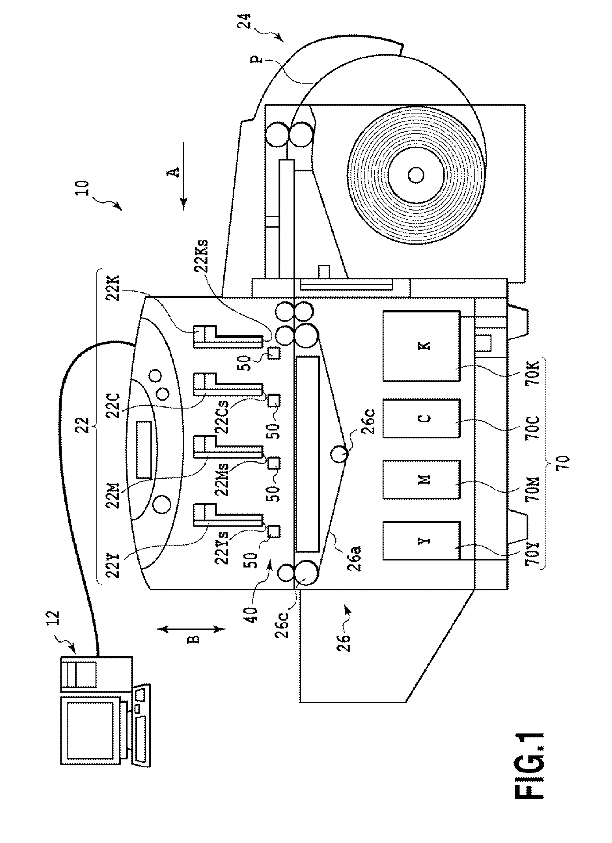
[0022]FIG. 1 is a side view schematically showing a first embodiment of an ink jet printing apparatus (hereinafter simply referred to as a printing apparatus) according to the present invention. A printing apparatus 10 according to the present embodiment is connected to a host apparatus 12 such as a personal computer to perform a printing operation based on image information transmitted by the host apparatus 12. The printing apparatus 10 includes four print heads (printing section) 22K, 22C, 22M, and 22Y arranged in a conveying direction (the direction of arrow A) of a pint medium (in this case, roll paper). The four print heads 22K, 22C, 22M, and 22Y eject a black ink, a cyan ink, a magenta ink, and a yellow ink, respectively. The four print heads 22K, 22C, 22M, and 22Y are line heads extending in a direction perpendicular to the sheet of FIG. 1. The four print heads 22K, 22C, 22M, and...

second embodiment

(Second Embodiment)

[0063]A second embodiment of the present invention will be described below with reference to the drawings. The basic configuration of the present embodiment is similar to the basic configuration of the first embodiment. Thus, only characteristic portions of the configuration will be described below.

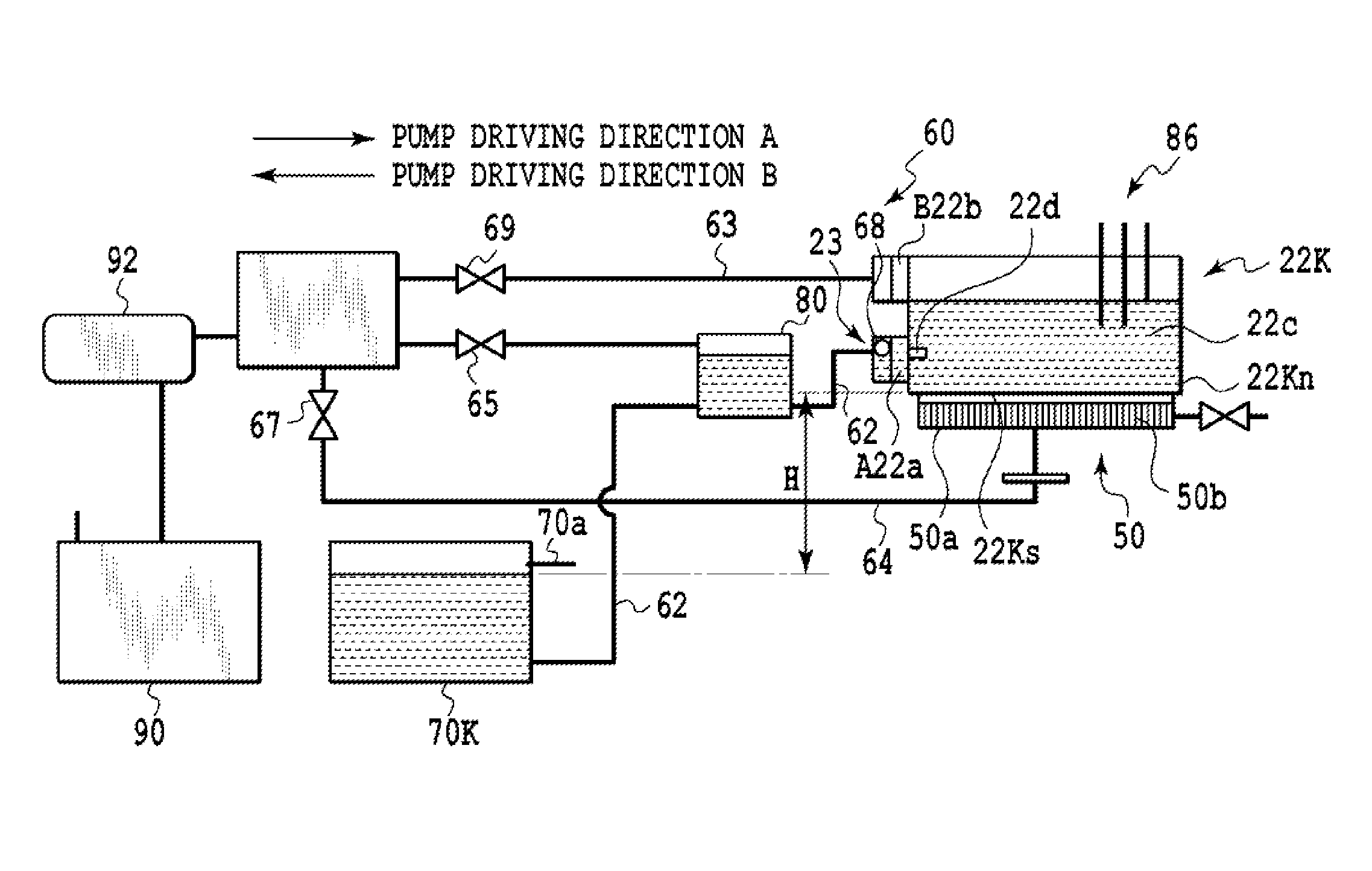
[0064]FIG. 10 is a diagram showing connections between print heads 22K, 22C, 22M, and 22Y and ink tanks according to the present embodiment. The first embodiment illustrates a form in which each ink supply apparatus corresponds to one print head. However, if a printing apparatus 10 (see FIG. 1) includes a plurality of built-in print heads, elements forming channels may be integrated together. According to the present embodiment, a bubble removal valve 65 and a recovery valve 67 are shared by the print heads 22K, 22C, 22M, and 22Y incorporated in the printing apparatus 10. That is, an operation of discharging ink through head nozzles 22Kn (see FIG. 3) as described in the...


PUM


Abstract

A printing apparatus includes a print head that ejects ink for printing, an ink tank from which ink is fed to the print head, a first channel provided between the print head and the ink tank to feed ink in the ink tank to the print head, a second channel through which the ink in the first channel is transferred, and a pump connected to the second channel to transfer the ink in the first channel. The pump allows air or the ink in the first channel to be discharged via the second channel.

Description

BACKGROUND OF THE INVENTION[0001]1. Field of the Invention[0002]The present invention relates to a printing apparatus with a print head that ejects ink through nozzles and an ink supply apparatus that supplies ink to the print head.[0003]2. Description of the Related Art[0004]Ink jet printing apparatuses which eject ink (ink droplets) to a print medium through ink ejection ports of a plurality of nozzles formed in a print head are widely used. A known technique for ejecting ink droplets through ink ejection ports in a print head involves supplying thermal energy associated with a driving pulse to ink in nozzles formed in the print head to cause film boiling in the ink so that the resultant bubbles allow ink droplets to be ejected through the nozzles. In an ink jet printing apparatus utilizing such an ink ejection technique, a large number of nozzles are arranged in the print head. Many types of ink associated with an image to be printed are ejected to a print medium through the plur...

Claims


Application Information

Patent Timeline
Patent Type & Authority Patents(United States)
IPC IPC(8): B41J2/165B41J2/19B41J2/18B41J2/175
CPCB41J2/19B41J2/175B41J2/18
Inventor TAKAHASHI, YUUICHIMUKAI, KAYONIIKURA, HIROKI
Owner COPYER
Why Eureka
Try Eureka