
Electric ground clamp with pivoted jaws and single attached adjusting bolt

a ground clamp and jaw technology, applied in the direction of coupling device connection, connection contact member material, coupling device details, etc., can solve the problems of loose parts which may be lost, difficult to disassemble and then reassemble the ground clamp around the electrical conduit in difficult to reach locations, and difficult to reach locations

Active Publication Date: 2011-09-20
BRIDGEPORT FITTINGS LLC
View PDF9 Cites 43 Cited by
  • Summary
  • Abstract
  • Description
  • Claims
  • Application Information

AI Technical Summary

Benefits of technology

[0010]It is an advantage of the invention that it can be securely fastened to different electrical conduits with a range of different sizes or diameters.
[0011]It is an advantage of the invention that a single fastener, bolt, or screw is used.
[0012]It is yet another advantage of the invention that the grounding clamp can be fitted over and tightened to an electrical conduit without any disassembly resulting in loose or separated parts that could be lost.
[0013]It is a feature of the invention that an elongated hole is formed on a distal end of the first hinged jaw.
[0014]It is another feature of the invention that a curved fork having a slot is formed on the distal end of an opposing hinged jaw with the curved fork shaped to receive a cylindrical nut.
[0015]It is yet another feature of the present invention that the first and second hinged jaws have different angled surfaces adapted to accommodate the different sizes or diameters of a wide variety of electrical conduits.

Problems solved by technology

While these prior ground clamps have been used successfully to ground electrical conduits, they are often difficult to install and often require disassembly of the ground clamp resulting in loose parts which may be lost.
Additionally, often different sized conduits must be accommodated that are often in difficult to reach locations.
Therefore, it may be difficult to disassemble and then reassemble a ground clamp around an electrical conduit in difficult to reach locations without loosing or dropping a part of the ground clamp.
This makes installation frustrating and difficult.

Method used


Image

  • Electric ground clamp with pivoted jaws and single attached adjusting bolt
  • Electric ground clamp with pivoted jaws and single attached adjusting bolt
  • Electric ground clamp with pivoted jaws and single attached adjusting bolt

Examples


Embodiment Construction

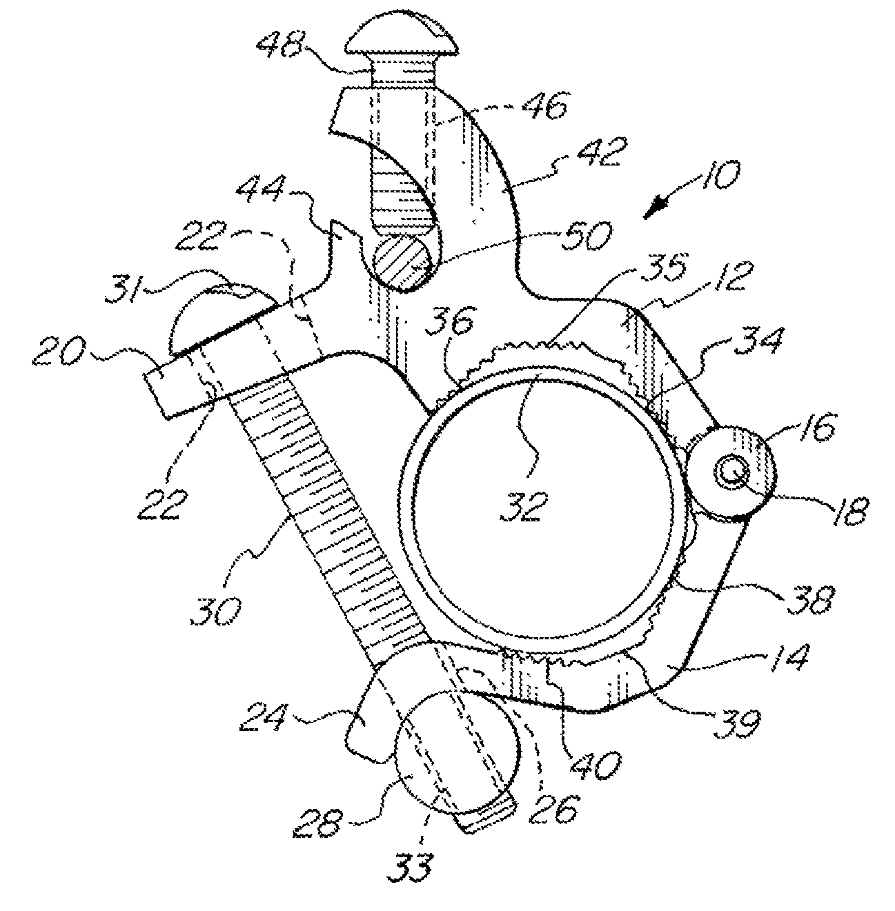
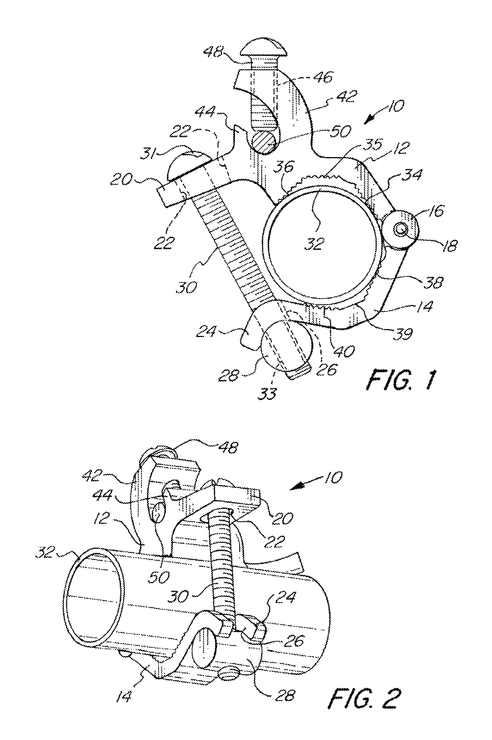
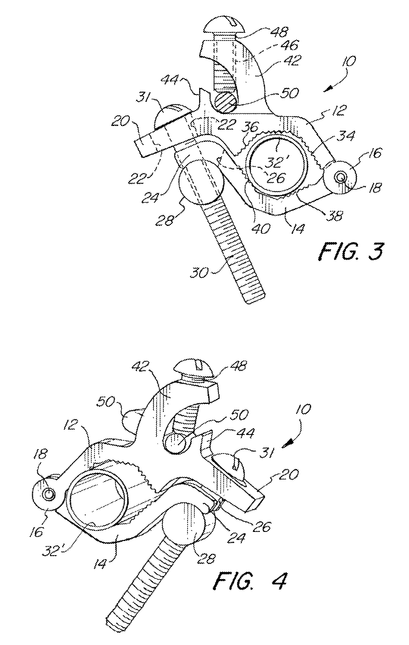
[0027]FIGS. 1-7B illustrate a first embodiment of the invention. In FIG. 1 the ground clamp 10 comprises a first jaw 12 coupled to a second jaw 14 by a hinge 16 and a hinge pin 18. The first jaw 12 has a first distal end 20 having an elongated hole 22 therein. The second jaw 14 has a second distal end forming a curve having a slot 26 formed therein forming a curved fork 24. A cylindrical nut 26 has a diameter substantially matching the curve or radius of the curved fork 24 formed on to the second distal end of the second jaw 14. The cylindrical nut 28 is held on the threaded portion or end 33 of bolt 30 having a head 31. The head 31 of the bolt 30 retains the bolt 30 within the elongated hole 22. The conduit 32, which may be electrical metallic tubing or EMT or a rigid conduit, is held between the first and second jaws 12 and 14. The first jaw 12 has a first inside angled jaw surface 34 and a first outside angled jaw surface 36 separated by a first intermediate surface 35. The secon...


PUM


Abstract

An adjustable ground clamp for easy positioning onto electric conduits of different diameters. A first and a second jaw are pivotally connected and have differently angled jaw surfaces. A distal end of the first jaw has an elongated hole and a distal end of the second jaw has a curved fork having a slot for receiving a bolt with a cylindrical nut. A fastener connects a ground conductor or wire to the ground clamp. The differently angled jaw surfaces, curved fork, cylindrical nut, and the elongated hole result in a ground clamp capable of securely holding electrical conduits of different sizes or diameters without disassembly. The jaws may be easily separated for placement of an electrical conduit without separating or detaching any parts from the ground clamp, making attachment to an electrical conduit quick, easy, and secure.

Description

FIELD OF THE INVENTION[0001]The present invention relates in general to an electric ground clamp for attaching to an electrical conduit, and more particularly to an adjustable clamp that is easily and quickly installed.BACKGROUND OF THE INVENTION[0002]In many electrical applications, it is often necessary to electrically ground a conduit. Often a ground clamp is attached to the conduit. A ground conductor or wire is then attached or connected to the ground clamp providing continuity or an electrical path to ground. Typically a compression clamp is used that often has two opposing screws or fasteners that are alternately tightened to draw two opposing sections of the clamp together substantially equally, so as to clamp down on the electrical conduit.[0003]One such ground clamp is disclosed in U.S. Pat. Des. 243,404 entitled “Ground Clamp” and issuing to Mooney et al on Feb. 15, 1977. Therein disclosed is a ground clamp having opposing portions, with a screw or a fastener on each end....

Claims


Application Information

Patent Timeline
IPC IPC(8): H01R4/66
CPCH01R4/36H01R4/40H01R4/42H01R4/643
Inventor SMITH, LAWRENCE J.
Owner BRIDGEPORT FITTINGS LLC
Learn More