
Cycloconverter generator

a technology of cycloconverter generator and generator, which is applied in the direction of electric generator control, speed sensing governor, machine/engine, etc., can solve the problems of disadvantageous and achieve the effect of preventing undesirable increase in fuel consumption and noise and stable ac power

Inactive Publication Date: 2011-09-20
HONDA MOTOR CO LTD
View PDF13 Cites 4 Cited by
  • Summary
  • Abstract
  • Description
  • Claims
  • Application Information

AI Technical Summary

Benefits of technology

The invention is a cycloconverter generator that can keep the frequency of AC power constant while the engine speed changes abruptly. This prevents an increase in fuel consumption and noise. The generator includes a magneto, three-phase output windings, and a bridge circuit with switching elements. The actuator controls the engine speed, and the required power detector and desired engine speed determiner determine the desired speed. The AC power generator generates the required power by turning on the switching elements based on the desired frequency. The technical effect of this invention is to improve the efficiency and stability of the cycloconverter generator.

Problems solved by technology

Hence, when the power required by the load is small, fuel consumption and noise are disadvantageously increased.

Method used


Image

  • Cycloconverter generator
  • Cycloconverter generator
  • Cycloconverter generator

Examples


Embodiment Construction

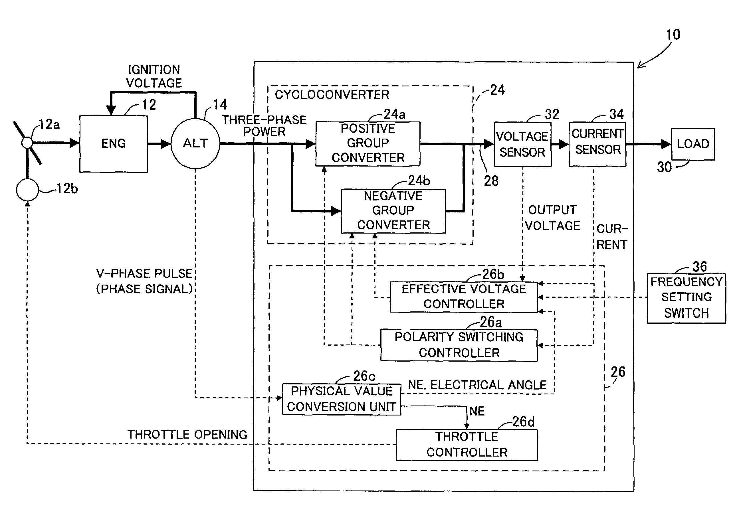
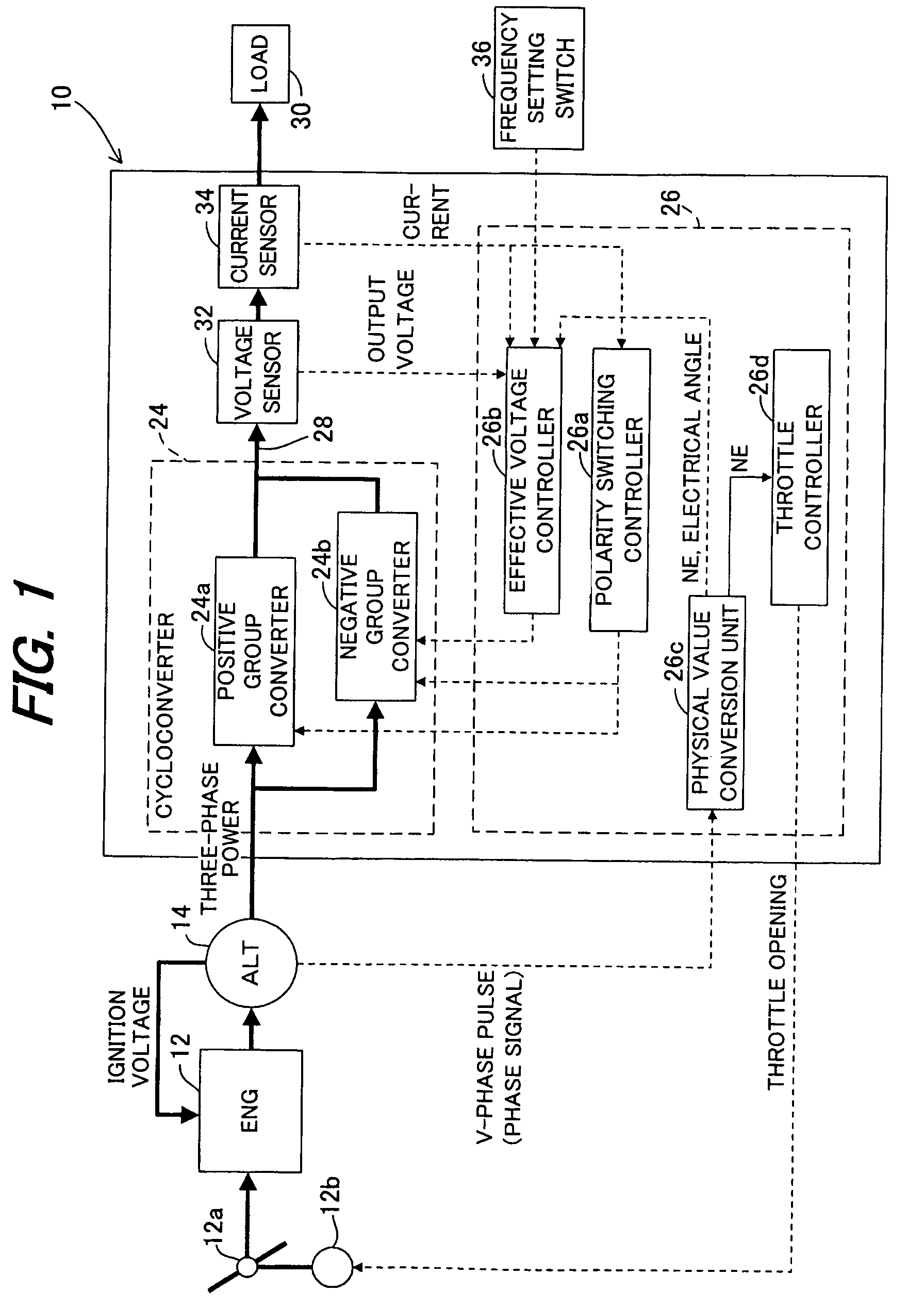
FIG. 1 is a block diagram showing the overall configuration of the cycloconverter generator according to the present invention.

Reference numeral 10 is assigned to the cycloconverter generator in FIG. 1. The generator 10 is equipped with an internal combustion engine 12 (named ENG in the drawing). It has rated outputs of AC 100 V-2.3 kVA and DC 12 V-10 A. The engine 12 is an air-cooled, spark ignition unit whose throttle valve 12a is moved by an actuator 12b comprising a stepper motor or the like. It is started using a recoil starter (not shown).

The generator 10 is equipped with a magneto or alternator 14 (named ALT in FIG. 1) that is driven by the engine 12.

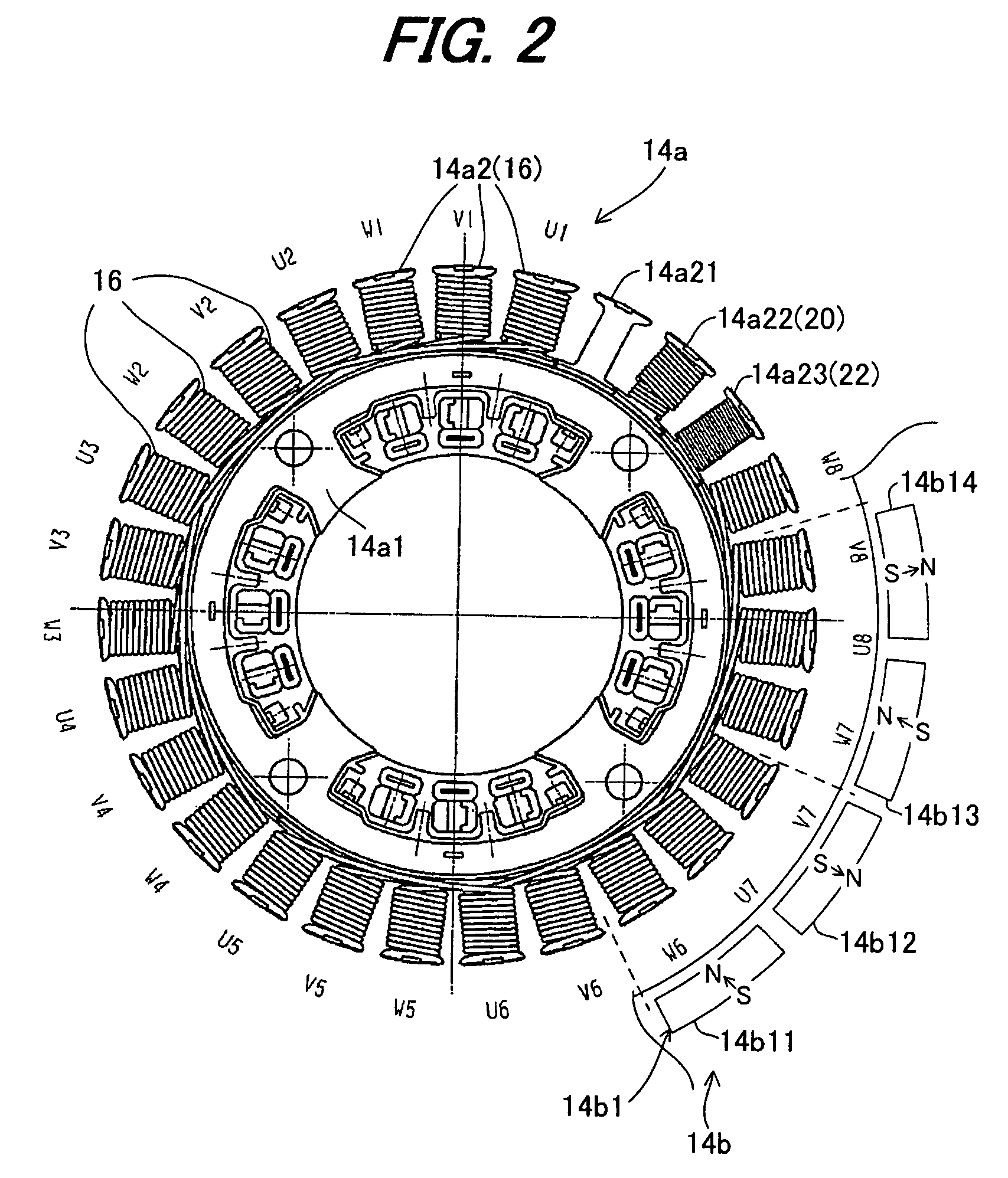
FIG. 2 is a plan view of a stator 14a of the magneto 14.

The stator 14a is equipped with a stator core 14a1 fastened near the cylinder head of the engine 12. As illustrated, twenty-seven teeth 14a2 are formed to project radially from the stator core 14a1. Twenty-four of the teeth 14a2 are wound with coils Un, Vn and Wn (n: 1 to 8)...


PUM


Abstract

In a cycloconverter generator, AC power required by the load is detected and a desired speed of the engine is determined based on the required AC power, operation of an actuator is controlled such that the engine speed becomes equal to the desired engine speed, and the required AC power is generated by turning on switching elements (thyristors) such that a number of the phase signal within one period of frequency of the AC power, becomes equal to a number determined by the desired engine speed, thereby preventing undesirable increase in fuel consumption and noise by operating the engine at a speed corresponding to required AC power and enabling to generate stable AC power even when the engine speed changes abruptly.

Description

BACKGROUND OF THE INVENTION1. Field of the InventionThis invention relates to a cycloconverter generator, namely a generator that converts AC power of a given frequency to another frequency for output.2. Description of the Related ArtThe cycloconverter generator that is driven by an internal combustion engine to produce an output by converting AC power of a given frequency to another frequency is well known. A description of the cycloconverter generator technology can be found, for example, in Japanese Patent No. 3,447,934. The cycloconverter generator described in this reference is equipped with thyristors bridge-connected in antiparallel connection to three-phase output windings in the positive and negative directions and generates single-phase alternating current of a desired frequency by turning on the thyristors at variable timing (width or angle) every half-period of the desired alternating current frequency.SUMMARY OF THE INVENTIONIn this type of cycloconverter generator, whe...

Claims


Application Information

Patent Timeline
Patent Type & Authority Patents(United States)
IPC IPC(8): H02P9/04
CPCB60L11/00H02M5/271H02P9/04H02P27/16H02P9/48H02P2101/45Y02T10/642B60L50/00Y02T10/64
Inventor INAGAWA, TOSHINORINAKAYAMA, SHINSAKUMASUBUCHI, YOSHINORI
Owner HONDA MOTOR CO LTD
Learn More