

Washing machine wiring to reduce mechanical timer contact welding
a technology of contact welding and control circuitry, which is applied in the direction of multiple dynamo-motor starters, motor/generator/converter stoppers, dynamo-electric converter control, etc., can solve the problems of increased stress on the design and manufacture of such appliances, increased complexity of control circuitry for such appliances, and negative word of mouth severely affecting sales, etc., to achieve the effect of increasing the cost of such controls or circuitry
- Summary
- Abstract
- Description
- Claims
- Application Information
AI Technical Summary
Benefits of technology
Problems solved by technology
Method used
Image

Examples
Embodiment Construction
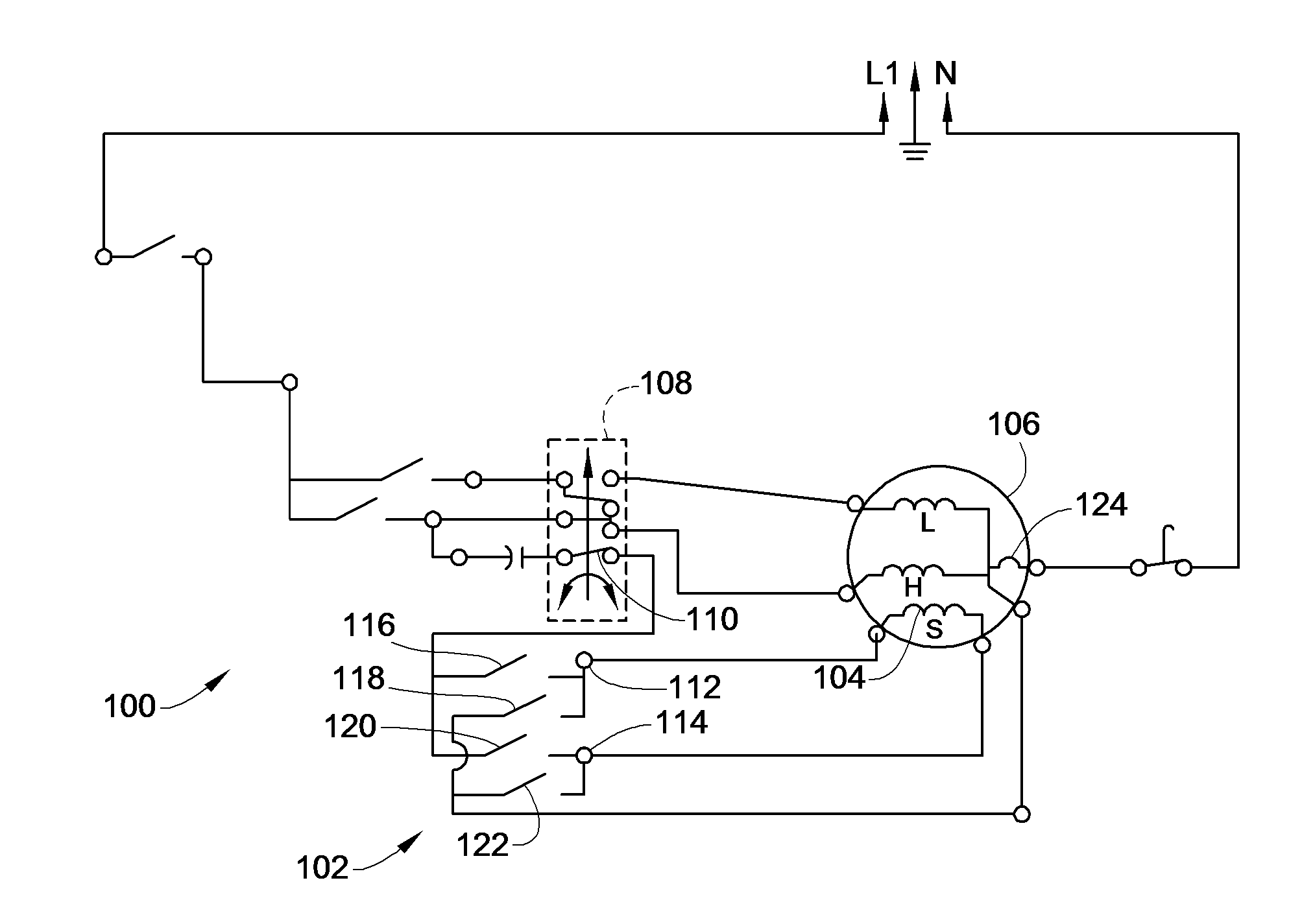
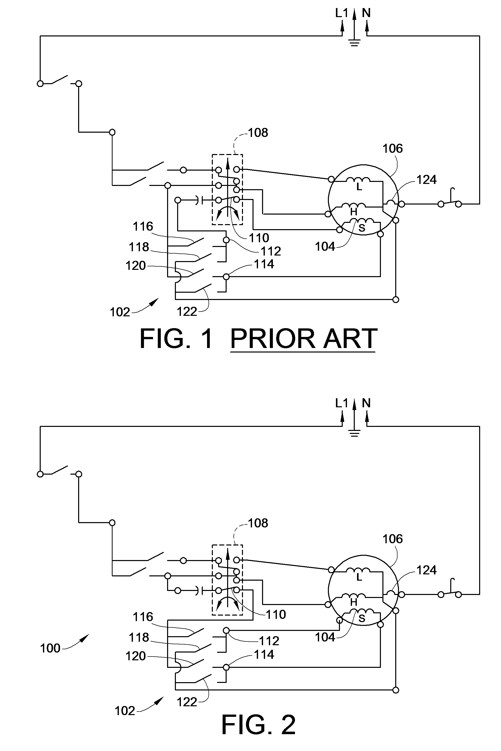
[0018]Turning now to the drawings, there is illustrated in FIG. 2 a simplified single line wiring schematic of one embodiment of the control wiring circuit for use in consumer or commercial washing machines constructed in accordance with the teachings of the present invention. In order to understand the operation and advantages provided by embodiments of the wiring of the present invention, operation of a washing machine must be understood. As such, and by way of example and not by limitation, the initial discussion that follows will provide a context of the appliance's operation to aid in a full understanding of the advantages and operation of embodiments of the instant invention.
[0019]In a typical washing machine a timer mechanism is used to control the various cycles that are necessary to complete the washing operation. These cycles include a filling operation, a washing or agitation operation, a drain and spin operation, a rinse operation, etc. Either during such cycles, operati...
PUM
 Abstract
Description
Claims
Application Information