
Washing Machine Wiring to Reduce Mechanical Timer Contact Welding

a technology of contact welding and control circuitry, which is applied in the direction of multiple dynamo-motor starters, motor/generator/converter stoppers, dynamo-electric converter control, etc., can solve the problems of increased stress on the design and manufacture of such appliances, increased complexity of control circuitry for such appliances, and negative word of mouth severely affecting sales, etc., to achieve the effect of increasing the cost of such controls or circuitry

Inactive Publication Date: 2010-07-08
ROBERTSHAW CONTROLS CO
View PDF11 Cites 3 Cited by
  • Summary
  • Abstract
  • Description
  • Claims
  • Application Information

AI Technical Summary

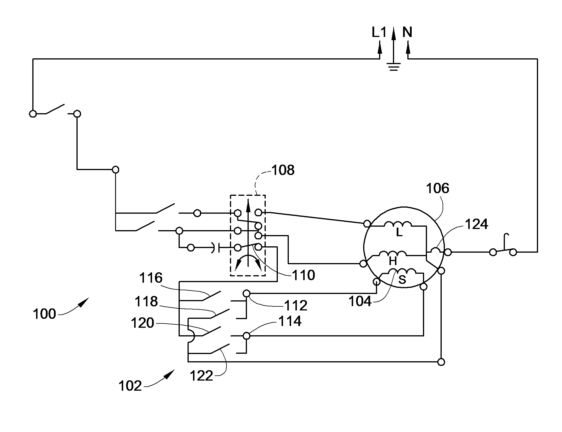
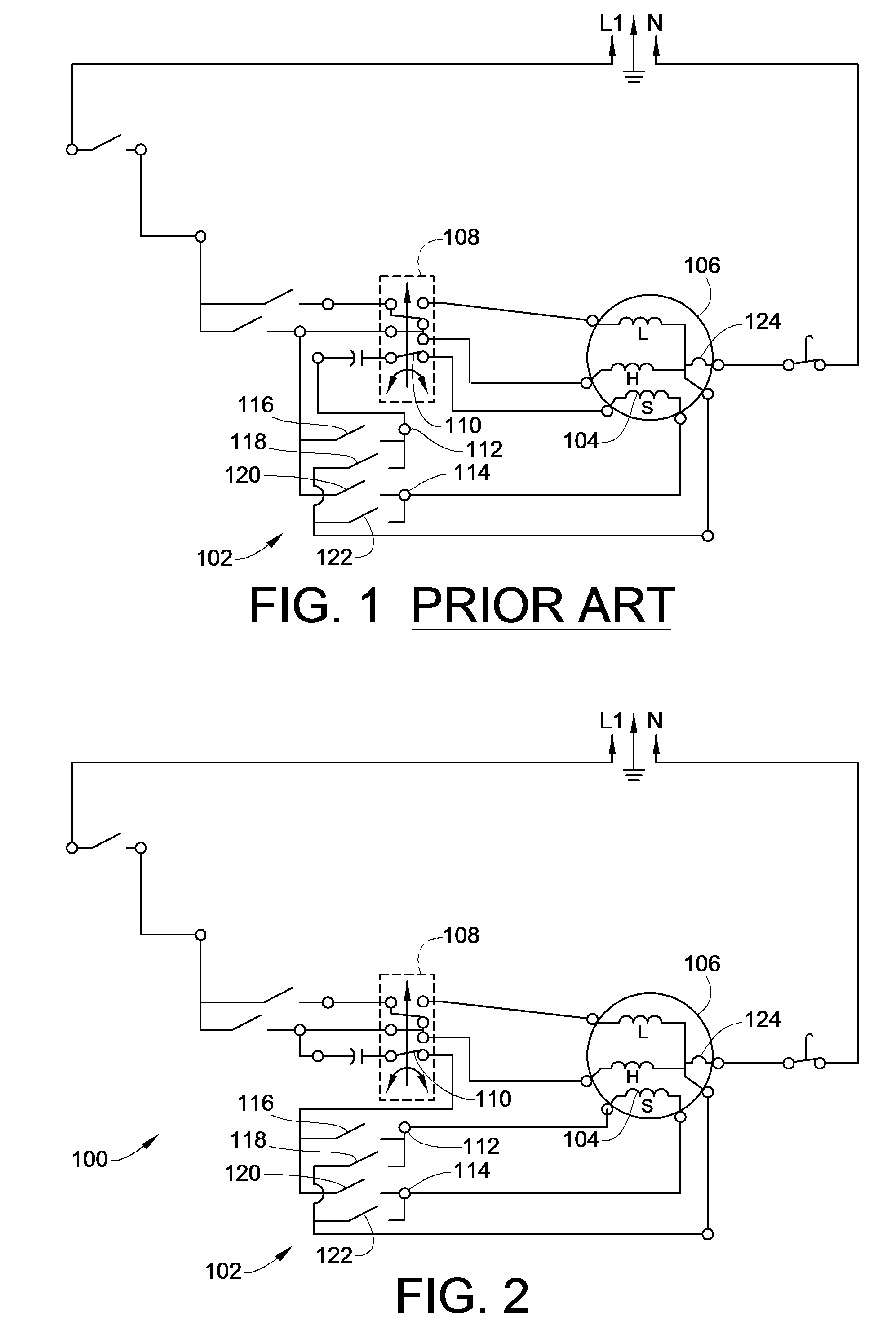
Benefits of technology

[0011]In view of the above, embodiments of the present invention provide new and improved control circuitry and system for consumer and commercial appliances. More particularly, embodiments of the present invention provide a new and improved circuitry and control system for consumer and commercial washing machines. Still more particularly, embodiments of the present invention provide new and improved control circuitry and system for consumer and commercial washing machines that overcome one or more of the problems existing in the art discussed above without unduly increasing the cost of such controls or circuitry by adding additional components thereto.
[0012]In one embodiment of the present invention, the control wiring for the washing machine utilizes the same switching assembly and the mechanical timer to switch the L1 and neutral side of 120 volt AC lines to change the direction of the main drive motor for the washing machine. However, the wiring of the switch contacts is coupled through the centrifugal switch of the washing machine. In such a manner, after the motor starts, the centrifugal switch opens as part of its normal operation, the L1 side of the 120 volt line is opened to the switching assembly. In this way, if three or four of the contacts bounce and touch due to the high shock or vibration in the quality testing cycle of the manufacturing process, a dead short does not result and no failure occurs.

Problems solved by technology

To keep pace with consumers' increasing desire for new features and in order to properly care for the various types of fabrics and garments being sold today, the complexity of the control circuitry for such appliances continues to increase.
At the same time, however, the increasing governmental requirements for energy efficiency and the consumer and competitive pressures to keep costs down have added increased stress on the design and manufacture of these appliances.
Indeed, with consumer preferences often driven by costs and quality, as opposed to traditional brand loyalty, manufactures must ensure that their appliances are competitively priced and operate properly when purchased and installed by a consumer.
As is recognized by such manufactures, any defect or failure to operate of a consumer appliance once purchased and installed will likely result in negative word of mouth severely impacting sales.
That is, settling for a quality control threshold of ninety-nine percent, and assuming for the sake of this example that one million units are produced, this ninety-nine percent quality control will result in 10,000 defective consumer appliances being sold and installed by consumers, who will then share their negative experiences with their friends and family.
This is simply unacceptable.
Unfortunately, to ease the ability of correcting any problems in the manufacturing process, each appliance is run before the final assembly is complete.
It has been observed that occasionally during this quality testing and final assembly operation that faults have occurred in the control wiring of the appliance.
Such faults, for example contact welding, may be attributed directly to excessive shock and vibration that may occur due to the excessive shock and vibration to which the entire appliance is subjected while moving down the conveyor system in the assembly plant while being tested.
Such failure significantly increase the overall cost of manufacturing, and may result in failed units being released for customer sale if the high shock failure occurs at the end of the testing cycle.
For washing machines, such as top loading washing machines, one common failure that can be directly attributed to the high vibration or shock seen during the final stages of the manufacturing process as the washing machine is being quality tested is a contact welding problem resulting from a dead short between the L1 and neutral (N) sides of the 120 volt AC lines that power the washing machine.
Such a dead short will typically result in the main circuit break on the assembly line power source to trip, possibly a tripped circuit breaker 124 in the motor through which this high current flows, and can cause welded contacts of the switching assembly 102.
If this fault occurs at the end of the quality testing cycle, it may go undetected and the washing machine may be released for sale to a consumer.
However, once installed by a consumer, the washing machine will not operate properly and will require a service call to replace the timer and / or reset the circuit breaker.
Not only will this result in a negative consumer experience, but it also increases the manufacture's warranty service costs and reduces the manufacture's quality reputation.

Method used


Image

  • Washing Machine Wiring to Reduce Mechanical Timer Contact Welding
  • Washing Machine Wiring to Reduce Mechanical Timer Contact Welding

Examples


Embodiment Construction

[0018]Turning now to the drawings, there is illustrated in FIG. 2 a simplified single line wiring schematic of one embodiment of the control wiring circuit for use in consumer or commercial washing machines constructed in accordance with the teachings of the present invention. In order to understand the operation and advantages provided by embodiments of the wiring of the present invention, operation of a washing machine must be understood. As such, and by way of example and not by limitation, the initial discussion that follows will provide a context of the appliance's operation to aid in a full understanding of the advantages and operation of embodiments of the instant invention.

[0019]In a typical washing machine a timer mechanism is used to control the various cycles that are necessary to complete the washing operation. These cycles include a filling operation, a washing or agitation operation, a drain and spin operation, a rinse operation, etc. Either during such cycles, operati...


PUM


Abstract

A control circuit for a washing machine that avoids contact bounce short circuit failures is provided. A washing machine that utilizes an induction motor including a starting winding used to start rotation of the motor at the beginning of a cycle. Such washing machines require that the motor be operated in both directions during different cycles. To enable such operation, a mechanical timer uses a pair of single pole, double throw switches in a switching assembly to reverse the L1 and neutral connections to the starter winding. To avoid the contact shorting problem, the control wiring runs either the L1 or neutral side of the voltage source, or both, through the centrifugal switch to open the input contact(s) once the motor has reached its operating speed. Then, if the switching assembly has L1 and N contacts touching at the same time, it will not result in a dead short.

Description

FIELD OF THE INVENTION[0001]The present invention relates generally to washing machine control circuitry, and more particularly to control wiring for washing machine control circuitry to minimize potential short circuit fault modes.BACKGROUND OF THE INVENTION[0002]Each year literally millions of consumer appliances, such as washing machines, are manufactured and sold in the United States. To keep pace with consumers' increasing desire for new features and in order to properly care for the various types of fabrics and garments being sold today, the complexity of the control circuitry for such appliances continues to increase. At the same time, however, the increasing governmental requirements for energy efficiency and the consumer and competitive pressures to keep costs down have added increased stress on the design and manufacture of these appliances. Indeed, with consumer preferences often driven by costs and quality, as opposed to traditional brand loyalty, manufactures must ensur...

Claims


Application Information

Patent Timeline
Patent Type & Authority Applications(United States)
IPC IPC(8): H02P1/58
CPCD06F37/306H02P1/58
Inventor PEARSON, JAMES E.ELKIN, RICHARD LOUIS
Owner ROBERTSHAW CONTROLS CO
Learn More