Proximity detection apparatus

Active Publication Date: 2007-10-25
SWELLING SOLUTIONS
View PDF69 Cites 28 Cited by
  • Summary
  • Abstract
  • Description
  • Claims
  • Application Information

AI Technical Summary

Benefits of technology

[0022] The term “hierarchical or ranked valve tree structure” means the that valves are arranged in ranks according to their proximity in the direction of fluid flow from the pump. The valve closest to the pump directs fluid flow to a further rank or ranks of valves. In this manner, the number of valves needed in the control unit to control the plurality of inflatable cells is reduced.
[0023] The provision of the ranked valve arrangement permits size reduction of the control unit by reducing the number of valves and, therefore, the space that they occupy and their power consumption. This permits the proximal positioning of the control unit assembly on or within an outer sleeve of a compression device. When placed discretely within an outer sleeve of the compression device, there are no external edges of the control unit which can be knocked or

Problems solved by technology

This in turn reduces the residence time for blood supplied to the lower limb and the severity of ischaemic episodes within the limb that can result in tissue breakdown.
This is often on the user's belt, placed in a pocket or carried around by hand which is inconvenient for the user.
Hence, the known control units are bulky and heavy.
Therefore, positioning of the unit in the device has not been practical because attaching the known control units to an outer surface of the compression device would result in an excessive weight burden impairing the mobility of the user.
Integral positioning is also unnecessary as most of the prior art devices are used in a hospital setting where mobility of the patient is not the main concern.
Were the control unit to be positioned on the devi

Method used


Image

  • Proximity detection apparatus
  • Proximity detection apparatus
  • Proximity detection apparatus

Examples


Embodiment Construction

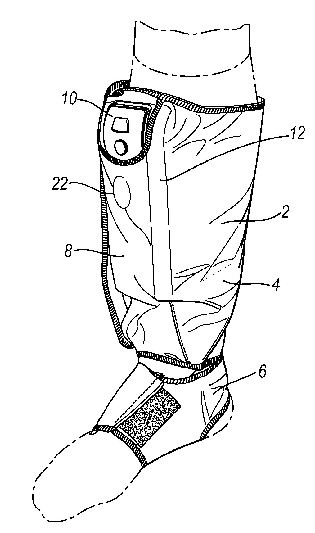
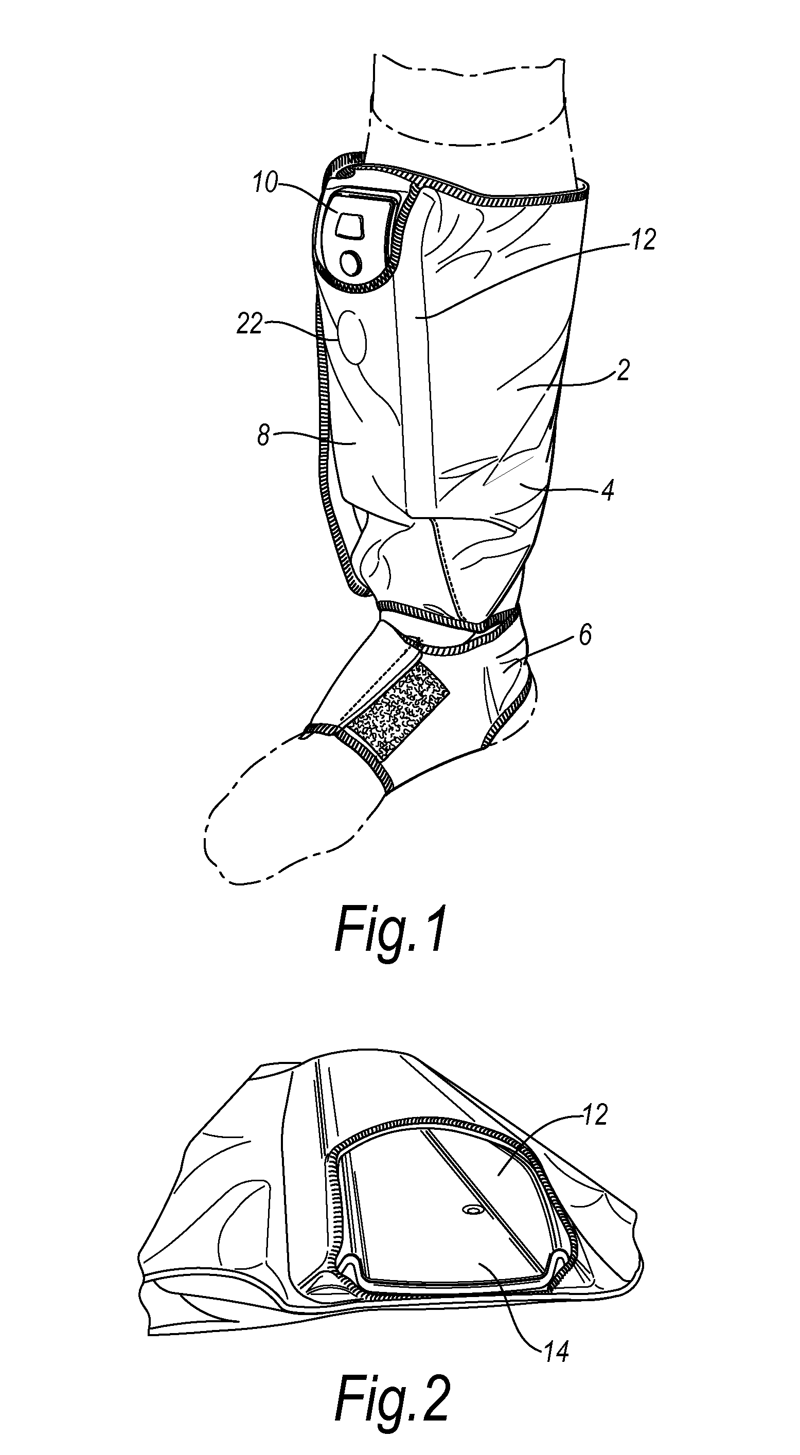
[0041] In FIG. 1 a control unit assembly and compression device according to an embodiment of the invention is shown worn on the leg of a patient. The device comprises a sleeve 2 having a leg cuff 4 connected to a foot cuff 6. The device also comprises a control unit assembly 8 comprising a control unit 10. The control unit 10 is small and when removed from the sleeve 2 may be hand held. The control unit 10 is battery powered and rechargeable so that it can be recharged when attached to or detached from the sleeve 2. FIG. 1 also shows the pouch 12 provided on sleeve 2 for receiving the control unit 10 and the low profile of the assembly. The control unit assembly follows the contour of the device and integrates the assembly into the device.

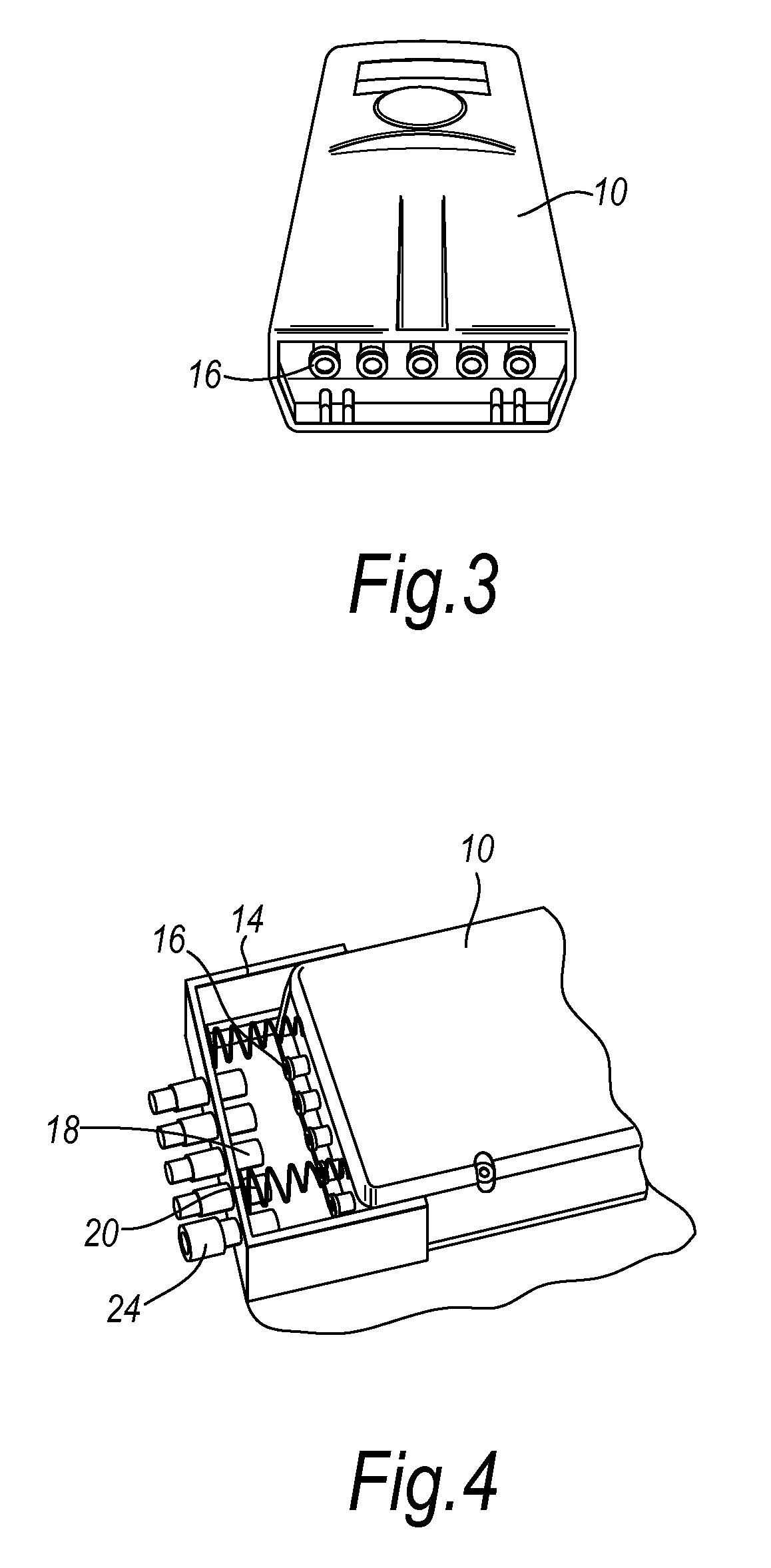
[0042]FIG. 2 is a perspective view taken from above the device with the control unit 10 removed showing the interior of the pouch 12 and the backing plate 14. The control unit 10 may be slidably engaged in the pouch 12 and retained in position by...


PUM

PropertyMeasurementUnit
Flow rateaaaaaaaaaa

Abstract

A control unit for a medical device wherein the control unit comprises a pump, a conduit and control means for controlling the flow of fluid from the pump through the conduit; and wherein the conduit is a rigid internal passage located in the control unit.

Description

BACKGROUND OF THE INVENTION [0001] This invention relates to a control unit assembly for use with a medical device and, particularly, a pneumatic medical device, such as a compression device for a limb. In particular, the invention relates to a control unit assembly for use with a mobile compression device suited for use in the treatment of venous leg ulcers, oedema, deep vein thrombosis and vascular disorders. [0002] Various medical devices are known that require inflation of one or more cells with fluid to a desired pressure, for example, compression devices which are used to apply pressure or pressure offloading devices such as mattresses or cushions which are used to even out pressure points. Compression devices are known for applying compressive pressure to a patient's limb. These types of devices are used to assist mainly in the prevention of deep vein thrombosis (DVT), vascular disorders and the reduction of oedema. Prior art devices are adapted for use in a hospital setting ...

Claims


Application Information

Patent Timeline
IPC IPC(8): A61H23/04
CPCA61B5/7475A61B2560/0456A61H9/0078A61H2201/0134A61H2201/0146A61H2201/5007A61H2205/10A61H2205/12A61H2201/5002
Inventor TUCKER, CARL ESTCOURTBAKER, TROY A.WILSON, GRAHAM PETERLINNANE, PATRICK GERRARDTABRON, IAN STEWARTBONNEFIN, WAYNE LEELOOF, STEFANBERGENS, THOMAS
Owner SWELLING SOLUTIONS
Why Eureka
Try Eureka