Control unit assembly

a control unit and control unit technology, applied in the field of pneumatic medical devices, can solve the problems of inconvenient use, tissue breakdown, and reduce the residence time of blood supplied to the lower limb, so as to improve patient compliance, reduce the number of valves needed in the control unit to control the plurality of inflatable cells, and improve the quality of patient life and control unit li

Active Publication Date: 2019-09-26
SWELLING SOLUTIONS
View PDF0 Cites 7 Cited by
  • Summary
  • Abstract
  • Description
  • Claims
  • Application Information

AI Technical Summary

Benefits of technology

[0012]The control unit of the invention has the advantage that, as the conduits are rigid it is possible to make a detachable connection between the control unit and a docking unit which is part of the medical device. This also makes it possible for there to be no external conduits between the control unit and the docking unit on the medical device. In this way, the control unit can be readily attached and detached from the medical device.
[0035]In this way, the air inlet to the pump is provided with a filter on the device side of the assembly. Thus, when the device has reached the end of its useful life and is replaced, the control unit is indirectly provided with a new filter. If the filter were placed in the control unit, it would not be replaced during the lifetime of the control unit without servicing of the unit. In addition, the provision of the filter on the device side of the assembly means that contamination of the control unit and its electrical circuitry is limited. If the filter were present in the control unit, during operation of the device unfiltered air would be drawn into the control unit at least as far as the filter. As the filter is external to the control unit, only filtered air is drawn into the control unit. This gives the advantage that reliability of the control unit may be improved.

Problems solved by technology

This in turn reduces the residence time for blood supplied to the lower limb and the severity of ischaemic episodes within the limb that can result in tissue breakdown.
This is often on the user's belt, placed in a pocket or carried around by hand which is inconvenient for the user.
Hence, the known control units are bulky and heavy.
Therefore, positioning of the unit in the device has not been practical because attaching the known control units to an outer surface of the compression device would result in an excessive weight burden impairing the mobility of the user.
Integral positioning is also unnecessary as most of the prior art devices are used in a hospital setting where mobility of the patient is not the main concern.
Were the control unit to be positioned on the device, weight would be localized at the attachment point of the device resulting in a weight imbalance on the compression device.
Also, a bulky control unit protruding from an outer surface of the compression device permits the unit to be knocked and possibly broken when the user is mobile and would not fit beneath clothing.
There are barriers to reducing the size of the control unit.
The conduits between the pump and the inflatable cells have in the past been external and would thus present a trip or tangle hazard.
The power consumption by the components in a typical hospital device would make the battery too large to be carried on the device itself and would make it too bulky to fit under clothing.
The above disadvantages may contribute to low patient compliance and limit use.

Method used


Image

  • Control unit assembly
  • Control unit assembly
  • Control unit assembly

Examples


Embodiment Construction

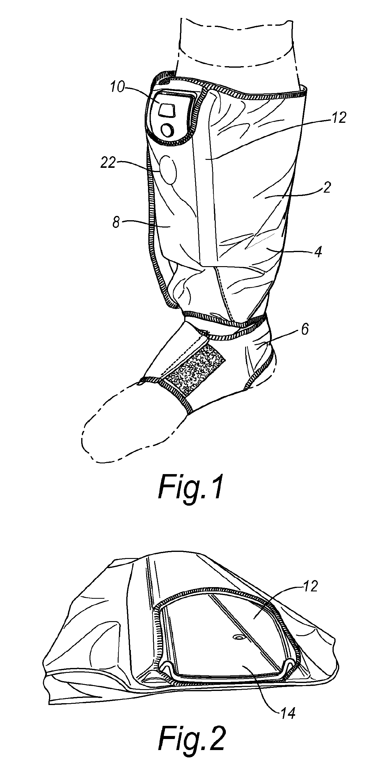
[0042]In FIG. 1 a control unit assembly and compression device according to an embodiment of the invention is shown worn on the leg of a patient. The device comprises a sleeve 2 having a leg cuff 4 connected to a foot cuff 6. The device also comprises a control unit assembly 8 comprising a control unit 10. The control unit 10 is small and when removed from the sleeve 2 may be hand held. The control unit 10 is battery powered and rechargeable so that it can be recharged when attached to or detached from the sleeve 2. FIG. 1 also shows the pouch 12 provided on sleeve 2 for receiving the control unit 10 and the low profile of the assembly. The control unit assembly follows the contour of the device and integrates the assembly into the device.

[0043]FIG. 2 is a perspective view taken from above the device with the control unit 10 removed showing the interior of the pouch 12 and the backing plate 14. The control unit 10 may be slidably engaged in the pouch 12 and retained in position by a...


PUM


Abstract

A control unit for a medical device wherein the control unit comprises a pump, a conduit and control means for controlling the flow of fluid from the pump through the conduit; and wherein the conduit is a rigid internal passage located in the control unit.

Description

BACKGROUND OF THE INVENTION[0001]This invention relates to a control unit assembly for use with a medical device and, particularly, a pneumatic medical device, such as a compression device for a limb. In particular, the invention relates to a control unit assembly for use with a mobile compression device suited for use in the treatment of venous leg ulcers, oedema, deep vein thrombosis and vascular disorders.[0002]Various medical devices are known that require inflation of one or more cells with fluid to a desired pressure, for example, compression devices which are used to apply pressure or pressure offloading devices such as mattresses or cushions which are used to even out pressure points. Compression devices are known for applying compressive pressure to a patient's limb. These types of devices are used to assist mainly in the prevention of deep vein thrombosis (DVT), vascular disorders and the reduction of oedema.[0003]Prior art devices are adapted for use in a hospital setting...

Claims


Application Information

Patent Timeline
Patent Type & Authority Applications(United States)
IPC IPC(8): A61B5/00A61H9/00
CPCA61H2205/12A61B2560/0456A61H2201/0146A61B5/7475A61H2201/0134A61H2205/10A61H2201/5007A61H9/0078A61H2201/5002A61H2201/0107
Inventor TUCKER, CARL ESTCOURTBAKER, TROY A.WILSON, GRAHAM PETERLINNANE, PATRICK GERRARDTABRON, IAN STEWARTBONNEFIN, WAYNE LEELOOF, STEFANBERGENS, THOMAS
Owner SWELLING SOLUTIONS
Why Eureka
Try Eureka