Walk-behind working machine

a working machine and walking wheel technology, applied in the field of walking behind working machines, can solve the problems of short life, easy loss, and difficulty in removing the battery and achieve the effects of preventing the loss of the battery locking member, facilitating the attachment/detachment of the battery, and removing the battery quickly from the battery holder

Active Publication Date: 2006-05-30
HONDA MOTOR CO LTD
View PDF8 Cites 6 Cited by
  • Summary
  • Abstract
  • Description
  • Claims
  • Application Information

AI Technical Summary

Benefits of technology

[0006]In view of the foregoing prior art problems, it is an object of the present invention to provide a walk-behind working machine which is arranged to appropriately protect an illumination section from wind and rain without requiring an increase in the number of necessary components.
[0007]It is another object of the present invention to provide a battery support structure for a walk-behind working machine which allows a battery to be readily attached and detached to and from a body of the machine without requiring a considerable amount of time and labor, which can prevent loss of a battery locking member, which allows a mounting position of the locking member to be chosen or determined relatively freely, and which can eliminate a need to form a resin coating on the surface of the locking member.
[0008]It is still another object of the present invention to provide a walk-behind working machine which permits mounting of a battery and illumination section with a reduced number of components and which can be constructed with an enhanced design freedom.

Problems solved by technology

However, the illumination section mounted on the upper portion of the cover would be exposed to wind and rain, thus resulting in a short life.
However, because the nuts have to be screwed onto the pair of stud bolts in the disclosed conventional battery support structure, attaching / detaching the battery would require a considerable amount of time and labor.
Further, because the locking member is removed from the stud bolts when the battery is to be detached, it tends to get lost easily.
Besides, where the locking member is formed of metal, the mounting position of the battery locking member would be greatly limited in order to avoid contact between terminals of the battery and the locking member and thereby prevent a short circuit.
Further, because the battery is held rearwardly of the auger housing and the illumination section is mounted via the stay on the left or right operating handle, the battery and illumination section are spaced a great distance from each other, which would make it difficult to secure a sufficient space for laying a harness (wires) for the illumination section and thereby result in a lowered design freedom.
However, there is still a possibility of snow and / or rain, having adhered to side wall surfaces of the battery, undesirably entering a gap between the battery and the battery cover to reach the upper end portion of the battery.
The same cover covering the engine may be extended to cover the entire battery in order to avoid the inconvenience, in which case, however, heat produced form the engine tends to transfer to the battery and adversely influence the battery.

Method used


Image

  • Walk-behind working machine
  • Walk-behind working machine
  • Walk-behind working machine

Examples


Embodiment Construction

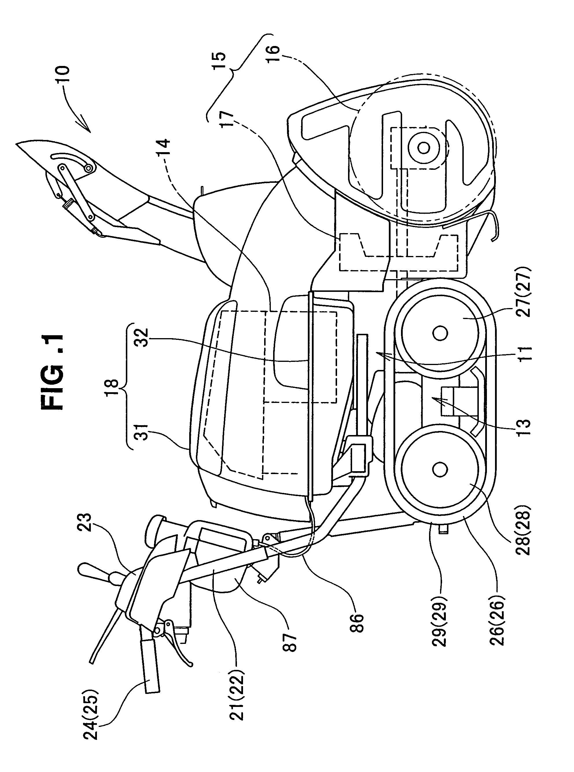
[0053]The working machine of the present invention will hereinafter be described as embodied as a snow removing machine, although it is not limited to snow removing machines.

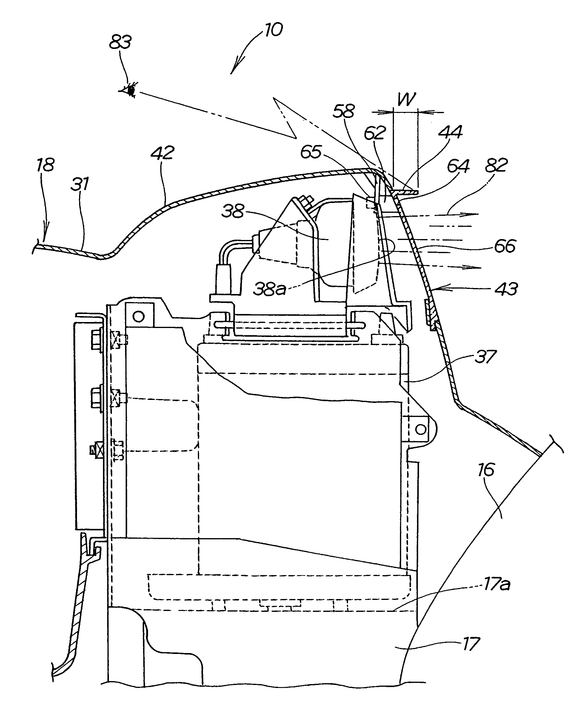
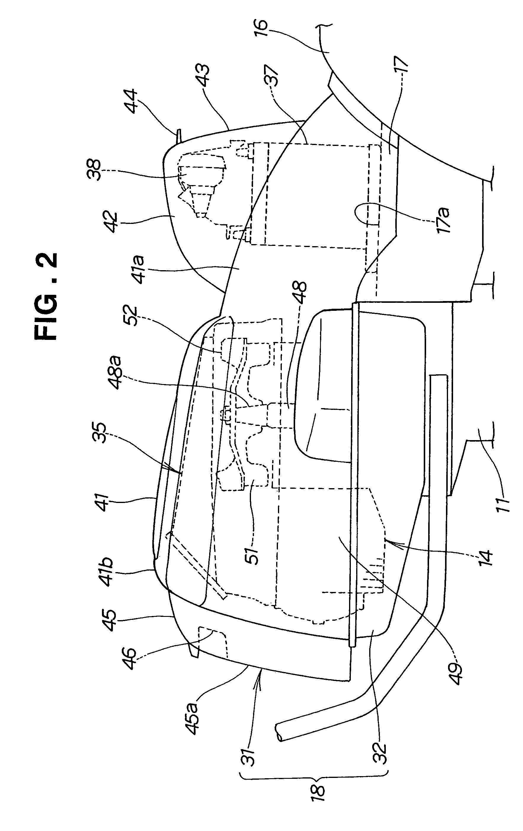
[0054]FIG. 1 is a side view of the snow removing machine in accordance with an embodiment of the present invention. The snow removing machine 10, one embodiment of the walk-behind working machine of the present invention, includes left and right electric motors (not shown in the figure; see 112 and 113 in FIG. 14) mounted to the left and right of a transmission case 11 forming a machine body, a traveling unit 13 connected to the left and right electric motors, an engine 14 disposed on the transmission case 11, and a snow removing unit (i.e., working unit) 15 driven by the engine 14 and secured to a front portion of the transmission case 11. Rear portion of the snow removing unit 15 and engine 14 are covered with a cover member 18, and left and right operating handles 21 and 22 extend rearwardly and upwardly from...


PUM


Abstract

A walk-behind working machine has a traveling unit, a working unit, an engine, and an illumination section disposed forwardly of the engine for projecting light. A cover member collectively covers the engine and the illumination section. The cover member has a light transmitting section for transmitting therethrough light projected by the illumination section. The light transmitting section or a portion of the cover member near the light transmitting section has at least one through-hole through which heat generated by at least one of the engine and the illuminating section is radiated.

Description

BACKGROUND OF THE INVENTIONField of the Invention[0001]The present invention relates to a walk-behind working machine, such as a snow removing machine, which is provided with an illumination section for illuminating an area in front of the machine. The present invention also relates to a battery support structure employed in the walk-behind working machine and including a battery holder into which a battery can be inserted from above or sideways and a battery locking member for holding the upper surface of the battery inserted in the battery holder. The present invention further relates to a small-size snow removing machine which includes an auger housing, blower housing, battery and illumination section.BACKGROUND INFORMATION[0002]Examples of the known walk-behind working machines include snow removing machines which are arranged to gather snow via an auger, throw up the gathered snow via a blower and discharges the thrown-up snow via a shooter. Of such snow removing machines, ther...

Claims


Application Information

Patent Timeline
Patent Type & Authority Patents(United States)
IPC IPC(8): E01H4/00E01H5/09B60Q1/04B62D51/04E01H5/04
CPCB60Q1/0458E01H5/04B62D51/04B60Q2800/20
Inventor ITOU, TOMOKIYUZURIHA, HIROMIAMANO, AISAKAI, SEISHUNAGAOKA, MASATOSHIYAMAMOTO, TAKAHIRO
Owner HONDA MOTOR CO LTD
Why Eureka
Try Eureka