

Medical imaging apparatus
- Summary
- Abstract
- Description
- Claims
- Application Information
AI Technical Summary
Benefits of technology
Problems solved by technology
Method used
Image

Examples
first embodiment
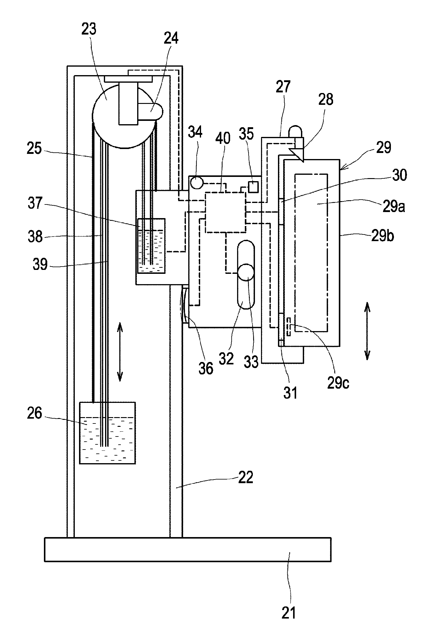
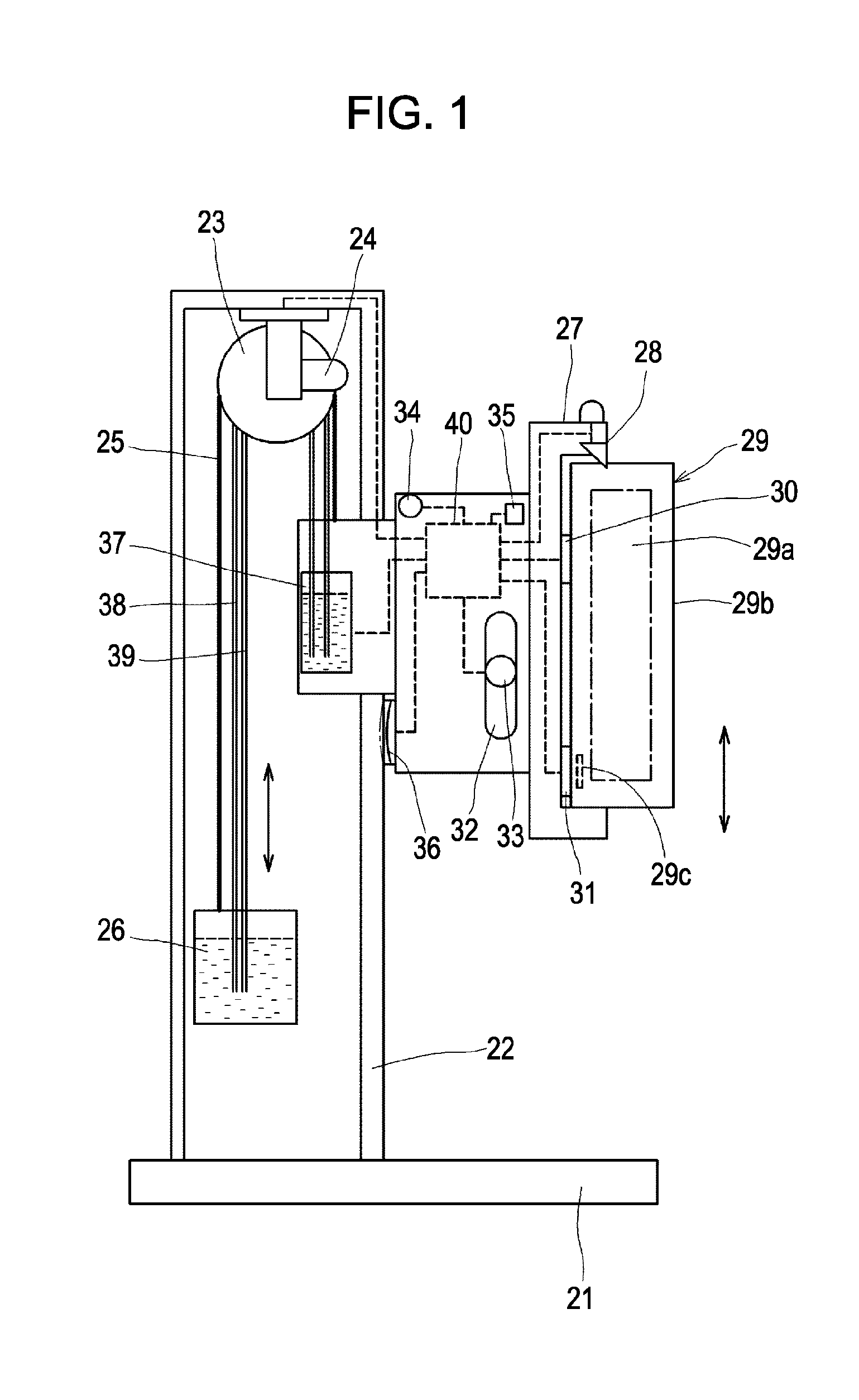
[0024]FIG. 1 is a configuration diagram showing a medical imaging apparatus with a vertical stand according to a first embodiment. A hollow column 22 is vertically provided on a pedestal 21. A pulley 23 is hung from an upper portion of the column 22. A safety lock portion 24 is attached to the pulley 23 to lock the pulley 23. A wire 25 is wound on the pulley 23. A first end of the wire 25 is connected to a weight 26, and a second end is connected to a holder 27, which is attached vertically movably along the column 22.
[0025]An imaging portion 29, which is one selected from a plurality of types of imaging portions for detecting two-dimensional images of subjects, is detachably attached to a front surface of the holder 27 via a detachment / attachment lock portion 28 driven by means of an actuator. Each of the imaging portions 29 includes a detector 29a, a housing 29b that covers the detector 29a, and a built-in identification plate 29c.
[0026]Also, a device attachment detecting unit 30...
second embodiment
[0035]FIG. 3 is a configuration diagram showing a medical imaging apparatus which uses a movable C-arm according to a second embodiment. A main body 42 has wheels 41. A column 43, vertical movement of which is adjustable, is vertically provided on the main body 42. A horizontal supporting portion 44, front-rear movement of which is adjustable, is attached on the column 43. A C-arm 46 is provided at the horizontal supporting portion 44 with a C-arm holder 45 interposed therebetween. The C-arm 46 is slidable in a direction indicated by an arrow along the shape of the C-arm 46. A radiation source 47 and an imaging portion 48 are attached to both ends of the C-arm 46 to face each other. In addition, an imaging portion detecting unit 49 that detects the presence and type of the imaging portion 48 is provided between the C-arm 46 and the imaging portion 48.
[0036]A lever 50 for vertically moving the column 43 is provided in a side surface of the main body 42. A lever 51 for moving the hori...
third embodiment
[0041]FIG. 5 is a configuration diagram showing a fundus photography apparatus of a medical imaging apparatus according to a third embodiment. A column 72 is vertically provided on a pedestal 71. A head unit 74 is held with a circular tilt arm 73 attached to the column 72. An optical base 75 is arranged in the head unit 74. The head unit 74 is movable along a curved surface of the tilt arm 73 while using a pair of guide rollers 76 as guides.
[0042]A weight adjustment spring mechanism 77 is provided in an upper portion of the head unit 74. An adjustment dial 78 is provided to adjust a spring force of the weight adjustment spring mechanism 77. The head unit 74 is configured to be movable while the weight balance is constantly kept. The weight adjustment is performed such that the head unit 74 is stopped at a desired position even when the head unit 74 is manually moved.
[0043]An imaging portion 79 is attached to a front surface of the head unit 74. A camera lock portion 80 inhibits the ...
PUM
 Abstract
Description
Claims
Application Information