Belt unit installed apparatus, image forming apparatus having the same, and method of installing/removing belt unit

a belt unit and installation apparatus technology, applied in the direction of electrographic process apparatus, instruments, optics, etc., can solve the problem of difficult detachment of the belt unit from the printer, and achieve the effect of easy attaching and detaching the belt uni

Inactive Publication Date: 2010-07-06
OKI DATA CORP
View PDF4 Cites 6 Cited by
  • Summary
  • Abstract
  • Description
  • Claims
  • Application Information

AI Technical Summary

Benefits of technology

[0012]In the belt unit installed apparatus, when the belt unit is detached from the apparatus frame, the protruding member pushes the urging member away from the receiving portion. Accordingly, it is possible to easily attach and detach the belt unit.

Problems solved by technology

Accordingly, it is difficult to detach the belt unit from the printer.

Method used


Image

  • Belt unit installed apparatus, image forming apparatus having the same, and method of installing/removing belt unit
  • Belt unit installed apparatus, image forming apparatus having the same, and method of installing/removing belt unit
  • Belt unit installed apparatus, image forming apparatus having the same, and method of installing/removing belt unit

Examples


first embodiment

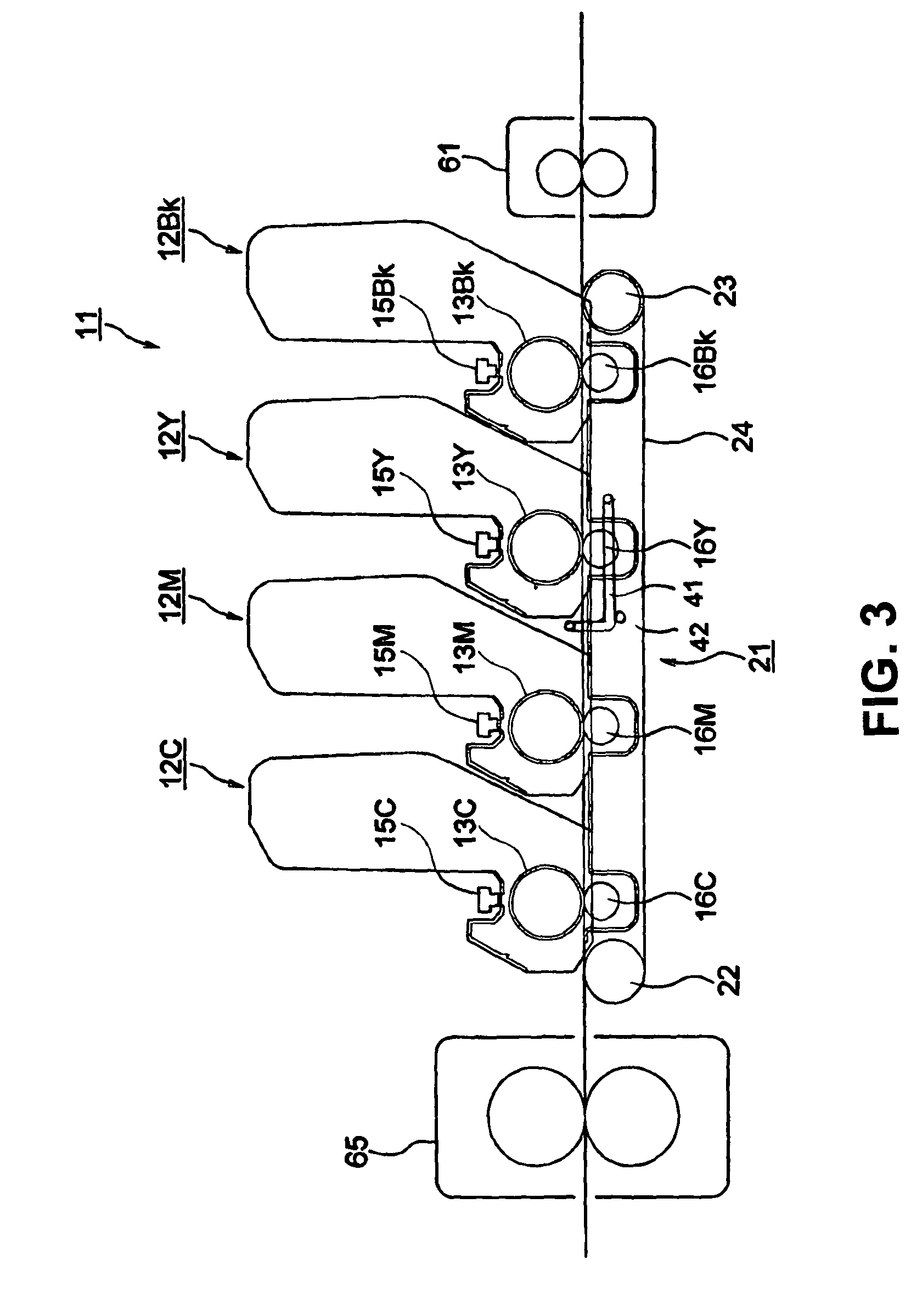
[0037]A first embodiment of the present invention will be explained. FIG. 3 is a schematic sectional view showing a color printer 11 according to the first embodiment of the present invention.

[0038]As shown in FIG. 3, the printer 11 includes image forming units 12Bk, 12Y, 12M, and 12C as image forming devices. The image forming units 12Bk, 12Y, 12M, and 12C are disposed in this order from an upstream side to a down stream side in a direction that a sheet as a recording medium is transported, and form developer images or toner images in black, yellow, magenta, and cyan, respectively.

[0039]The image forming units 12Bk, 12Y, 12M, and 12C include photosensitive drums 13Bk, 13Y, 13M, and 13C, and further include charge rollers (not shown), developing rollers (not shown), and cleaning blades (not shown) respectively contacting with the photosensitive drums 13Bk, 13Y, 13M, and 13C.

[0040]The charge rollers as charge devices uniformly and consistently charge surfaces of the photosensitive dr...

second embodiment

[0076]A second embodiment of the present invention will be explained next. Components in the second embodiment similar to those in the first embodiment are designated with the same reference numerals, and explanations thereof are omitted. The components similar to those in the first embodiment provide the similar effects.

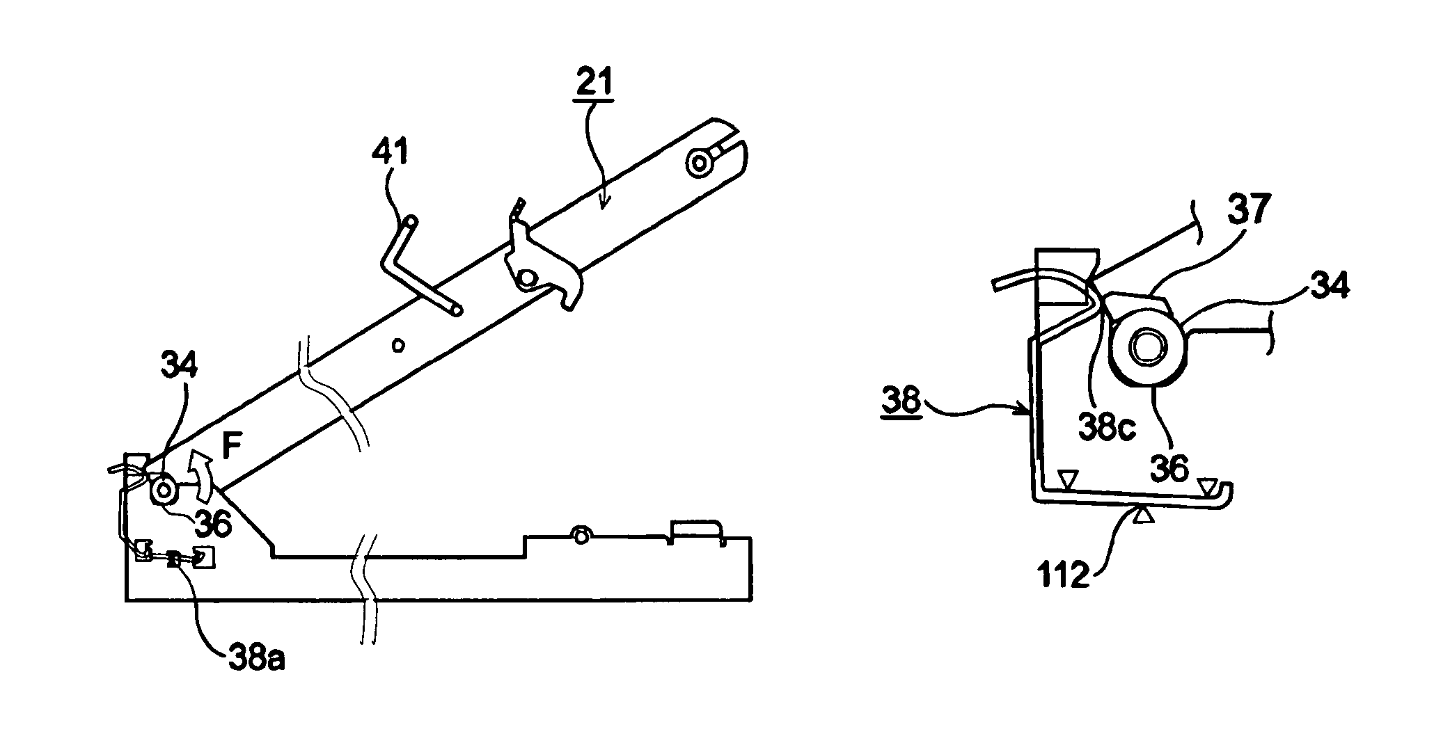
[0077]FIG. 17 is a schematic enlarged view showing a belt unit in an attached state according to the second embodiment of the present invention.

[0078]As shown in FIG. 17, the bearing receiving portion 36 has wall surfaces 36a and 36b, and the wall surface 36b at the side of the fixing device 65 (FIG. 3) extends upward. A recess portion 36e is formed in the wall surface 36b at a position facing the protruding member 37 as a pressing device when the belt unit 21 is attached to the frame 51. A curved portion 37a as a chamfered portion is formed on an upper end portion of the protruding member 37 at the side of the fixing device 65.

[0079]In the embodiment, a tapered sur...


PUM


Abstract

A belt unit installed apparatus includes an apparatus frame; a belt unit attached to the apparatus frame, said belt unit having a first roller, a second roller, a belt placed between the first roller and the second roller, and a belt frame for supporting the first roller and the second roller; an engaging member disposed on the belt frame for engaging the apparatus frame; a receiving portion formed in the apparatus frame for engaging the engaging member; and an urging member disposed on the apparatus frame for urging the engaging member. The engaging member maintains an engagement state relative to the receiving portion when the engaging member engages the receiving portion.

Description

BACKGROUND OF THE INVENTION AND RELATED ART STATEMENT[0001]The present invention relates to a belt unit installed apparatus, an image forming apparatus having the belt unit installed apparatus, and a method of installing / removing a belt unit.[0002]As an example of a belt unit installed apparatus, in which a belt unit is installed, there is provided an image forming apparatus of electronic-photography type such as a printer, a copier, a facsimile, and a multifunction device.[0003]In a conventional image forming apparatus such as a color printer, an image is formed through the following process. First, a charge roller charges a surface of a photosensitive drum. An exposure device such as an LED head exposes the surface of the photosensitive drum to form a static latent image or a latent image thereon. A developing roller attaches a thin layer of toner to the static latent image to form a toner image. A transfer roller transfers the toner image to a sheet. A fixing device fixes the ton...

Claims


Application Information

Patent Timeline
Patent Type & Authority Patents(United States)
IPC IPC(8): B65G21/20G03G21/16
CPCG03G15/0194G03G2215/0119G03G2215/0141G03G15/0189G03G2215/0193
Inventor SHOJI, YUICHI
Owner OKI DATA CORP
Why Eureka
Try Eureka