
Fluted firearm barrel

a barrel and flue technology, applied in the field of flue barrels, can solve the problems of conventional flutes not providing the desired amount of weight reduction, conventional add-ons, and conventional flutes not providing sufficient surface area, etc., to achieve the effect of maintaining barrel stiffness and improving barrel cooling

Inactive Publication Date: 2011-09-27
UNITED STATES OF AMERICA THE AS REPRESENTED BY THE SEC OF THE ARMY
View PDF44 Cites 29 Cited by
  • Summary
  • Abstract
  • Description
  • Claims
  • Application Information

AI Technical Summary

Benefits of technology

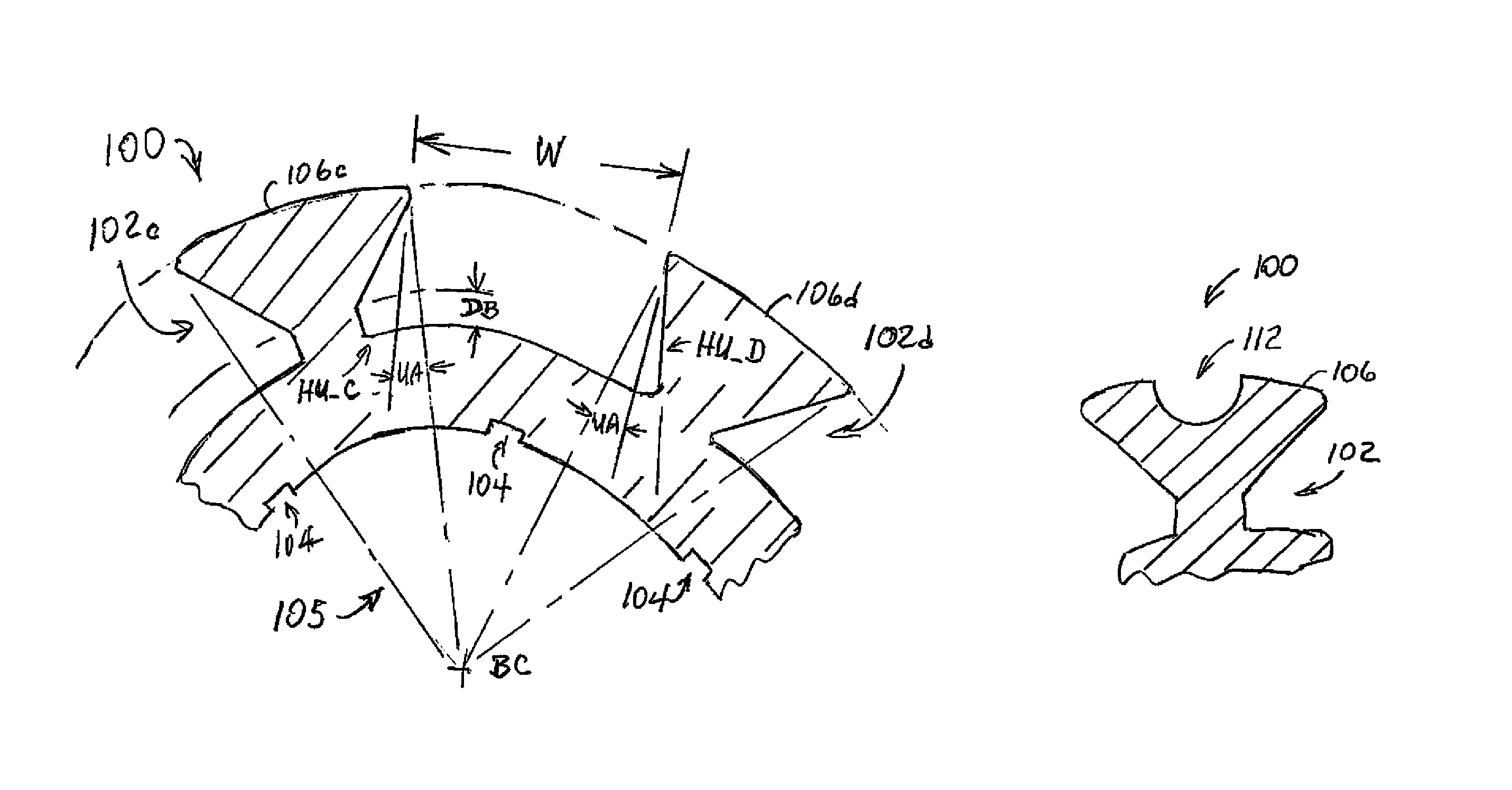
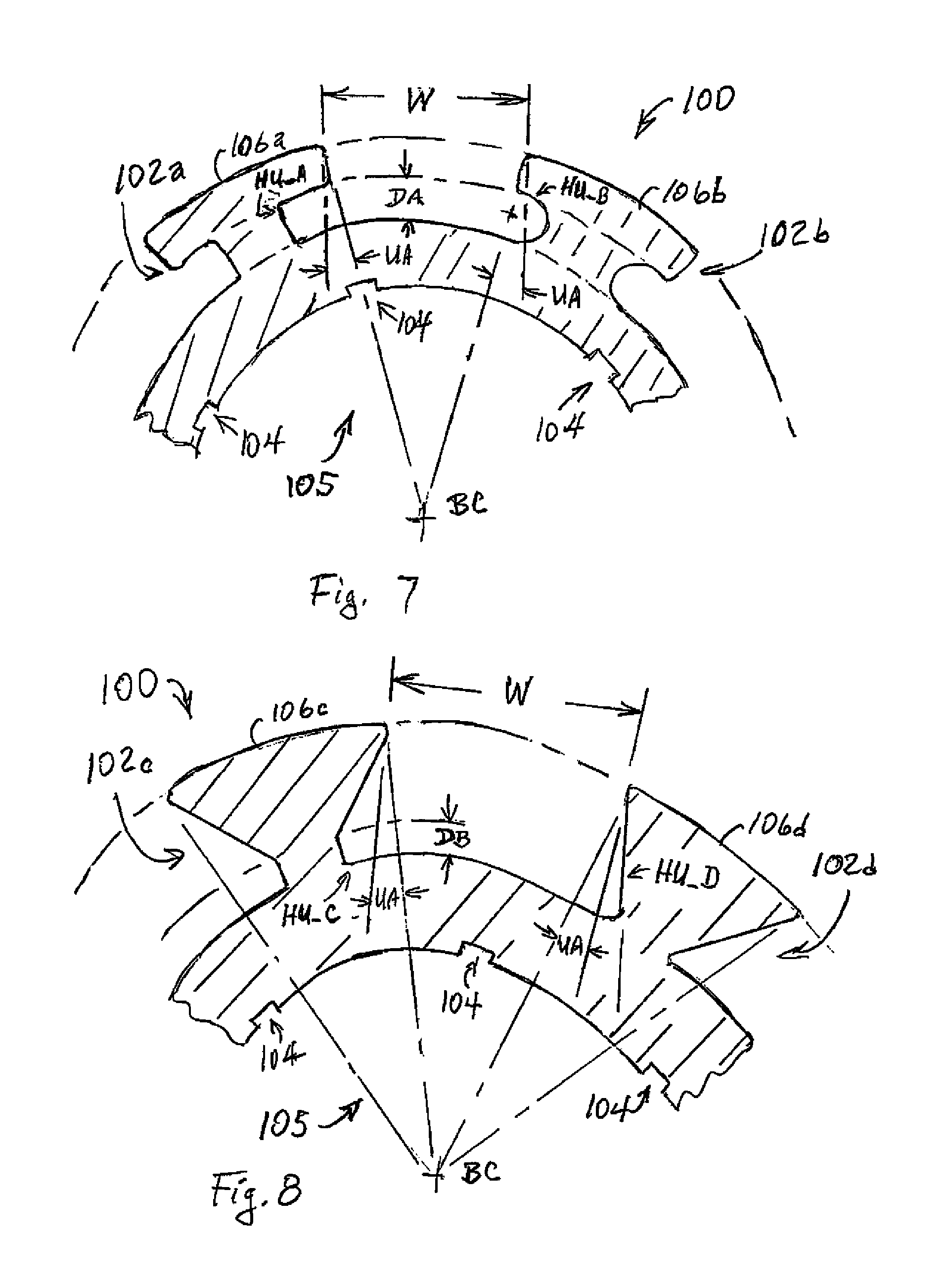
[0015]The present invention may be directed to a firearm barrel having barrel flutes on the outer surface of the barrel where (i) the barrel flutes are undercut relative to an outward radial vector from the center of the barrel at an arcuate radial distance that exceeds the arcuate radial distance of an undercut produced by a straight walled flute cutter (i.e., the barrel flutes are hyper-undercut), and (ii) at least one of (a) the barrel flutes are at a spiral longitudinally along the barrel and have a spiral that is tighter (closer) at the muzzle end of the barrel than at the chamber end, (b) the barrel flutes are wider at the muzzle end of the barrel than at the chamber end, and (c) there are more flutes formed at the muzzle end of the barrel than at the chamber end. The present invention may further provide a firearm barrel having primary and secondary barrel flutes on the outer surface of the barrel. The present invention may also be directed to a method of producing such a firearm barrel. The present invention may provide enhanced barrel cooling while maintaining barrel stiffness.
[0027]The barrel flute undercuts may be rough cut or abraded to increase radiation efficiency.
[0028]The barrel flutes may be finished in flat black to increase radiation efficiency.
[0030]Also according to the present invention, method of reducing the weight of a firearm barrel having an outer surface, a bore, a muzzle end, and a chamber end is provided. The method comprises forming barrel flutes having respective ribs on the outer surface of the barrel, and

Problems solved by technology

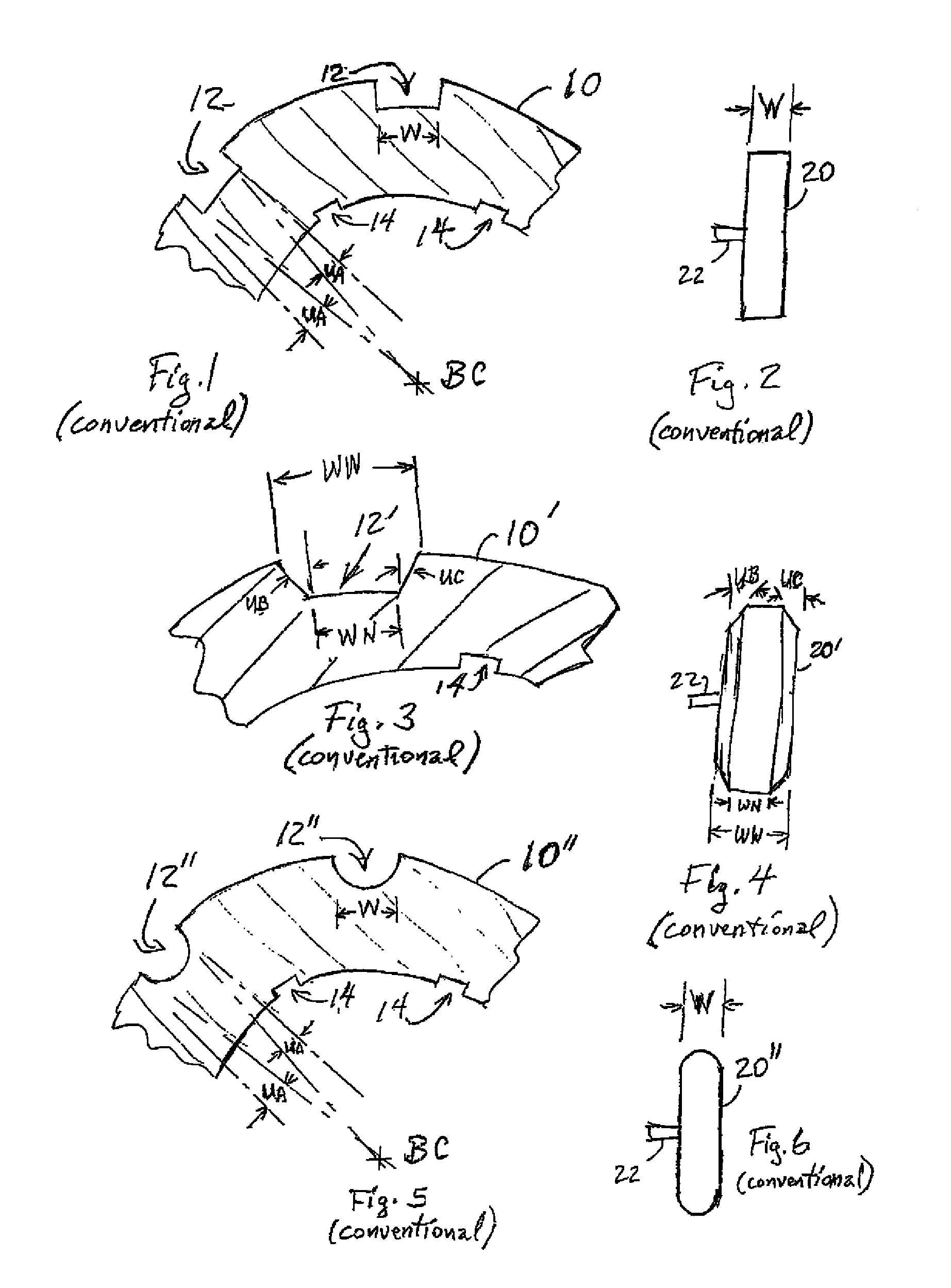
However, conventional flutes may fail to provide a sufficient increase in surface area over that of an unfluted barrel to provide a desired amount of heat dissipation while maintaining barrel stiffness close to that of an unfluted barrel.
Conventional flutes may fail to provide the desired amount of weight reduction.
Conventional add-on (i.e., accessory) cooling devices such as bolt-on heat sinks may fail to provide a sufficient combination of heat dissipation and barrel stiffness as such devices are not integral to the barrel.
Such add-on devices increase the weight of the weapon.

Method used


Image

  • Fluted firearm barrel
  • Fluted firearm barrel
  • Fluted firearm barrel

Examples


Embodiment Construction

)

[0052]With reference to the Figures, the preferred embodiments of the present invention will now be described in detail. Generally, the present invention provides an improved fluted firearm barrel, and a method for making the improved fluted firearm barrel.

[0053]The present invention is generally directed to a firearm barrel having barrel flutes on the outer surface of the barrel where the barrel flutes are undercut relative to an outward radial vector from the center of the barrel at an arcuate radial distance that exceeds the arcuate radial distance of an undercut produced by a straight walled flute cutter (i.e., the barrel flutes are hyper-undercut). In various example implementations, (i) the barrel flutes are at a spiral longitudinally along the barrel the spiral is tighter (closer) at the muzzle end of the barrel than at the chamber end, (ii) the barrel flutes are wider at the muzzle end of the barrel than at the chamber end, and (iii) there are more flutes formed at the muzz...


PUM


Abstract

A firearm barrel having barrel flutes on the outer surface of the barrel where the barrel flutes are undercut relative to an outward radial vector from the center of the barrel at an arcuate radial distance that exceeds the arcuate radial distance of an undercut produced by a straight walled flute cutter such that the barrel flutes are hyper-undercut.

Description

GOVERNMENT INTEREST[0001]The inventions described herein may be made, used and licensed by and for the U.S. Government for U.S. Government purposes.BACKGROUND OF THE INVENTION[0002]1. Field of the Invention[0003]The present invention generally relates to a fluted firearm barrel.[0004]2. Background Art[0005]Typical conventional firearm barrel technology includes U.S. Pat. Nos. 3,738,044; 3,483,794; 4,982,648; 5,054,224; 5,448,848; 5,794,374; 6,314,857; 6,324,780; 6,381,895; 6,508,159; and 6,574,898.[0006]Referring to FIG. 1 a diagram illustrating a fragmented sectional view of a portion of a conventional firearm barrel 10 having conventional straight cut flutes (i.e., flutes with undercut, UA) 12 is shown. The barrel 10 is substantially cylindrical with a center of the radial section, BC. When a straight walled cutter (see, for example, FIG. 2) is used to produce the fluting 12, the undercut, UA, is the additional material removed at an arcuate radial distance beyond (outside of) rad...

Claims


Application Information

Patent Timeline
IPC IPC(8): F41A21/00
CPCF41A21/24
Inventor SAUR, THOMAS W.
Owner UNITED STATES OF AMERICA THE AS REPRESENTED BY THE SEC OF THE ARMY
Learn More