Buoyant bumper apparatus for absorbing water vessel impact against pilings

a technology for water vessels and bumpers, which is applied in the direction of hulls, vessel cleaning, vessel construction, etc., can solve the problems of direct damage and direct hitting of boats with pilings

Inactive Publication Date: 2011-09-27
KATULKA MICHAEL A
View PDF3 Cites 15 Cited by
  • Summary
  • Abstract
  • Description
  • Claims
  • Application Information

AI Technical Summary

Benefits of technology

[0014]Each block guide preferably has a substantially L-shaped cross-section with a guide side panel abutting and fastened to a corresponding upright side of the bumper block and extends beyond the bumper block toward the roller rack, and has a guide flange angling inwardly from the guide side panel toward the opposing guide flange and spaced from the bumper block, and where the first and second guide flanges are fitted behind corresponding first and second rail flanges and the guide flanges thereby hold the bumper block substantially against the rollers while permitting the bumper block to slide vertically along the roller rack. The bumper block preferably is vertically elongate. The float preferably is formed of one of: buoyant material and a hollow member and has sufficient buoyancy to cause the bumper assembly to rise and fall with the tidal height of the water around the piling.

Problems solved by technology

A problem with these prior bumpers has been that, as the tide rises or falls, the part of the boat striking the piling may be elevated or lowered out of alignment with the bumper so that the boat strikes the piling directly and is damaged.

Method used


Image

  • Buoyant bumper apparatus for absorbing water vessel impact against pilings
  • Buoyant bumper apparatus for absorbing water vessel impact against pilings
  • Buoyant bumper apparatus for absorbing water vessel impact against pilings

Examples


first preferred embodiment

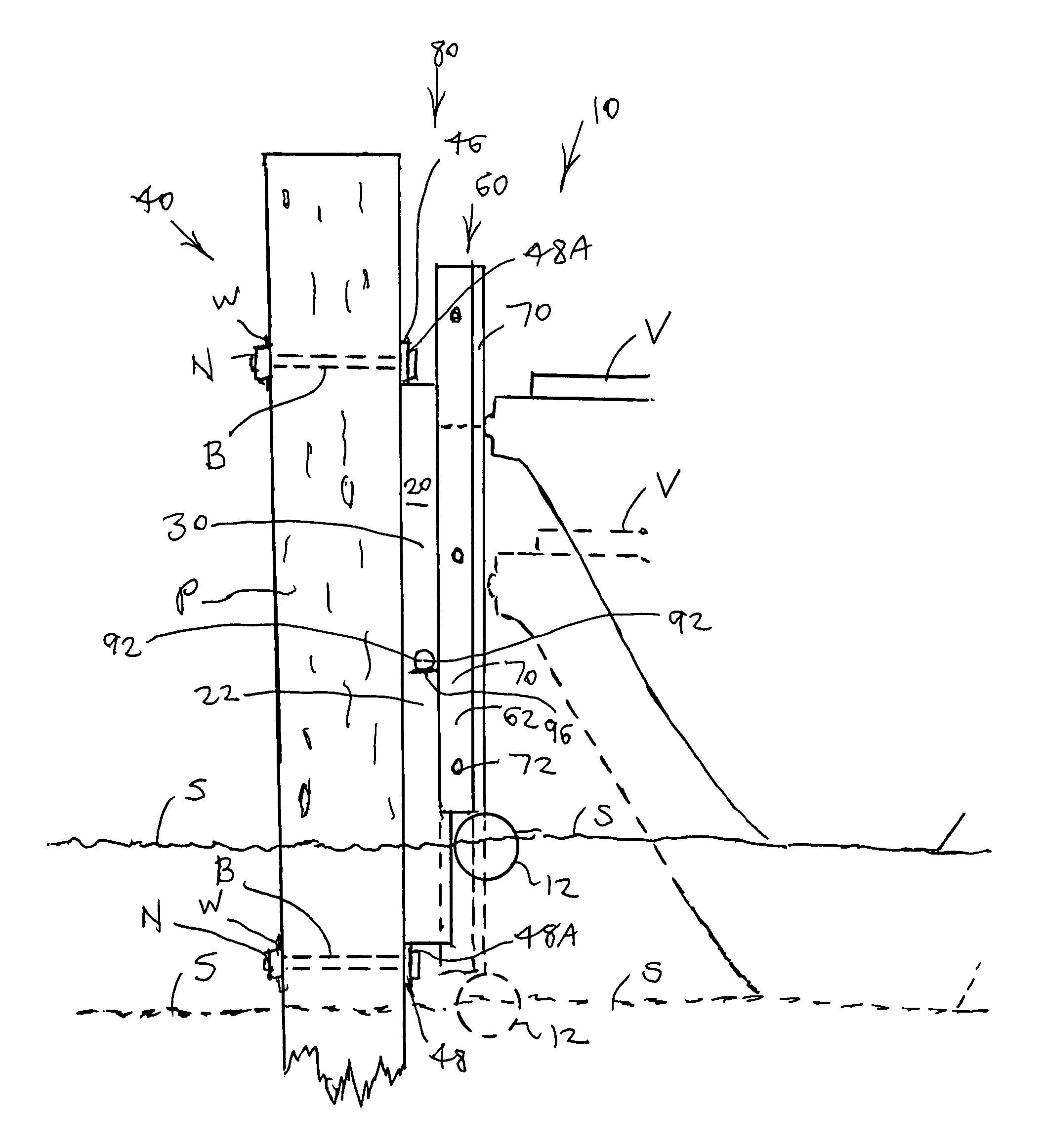
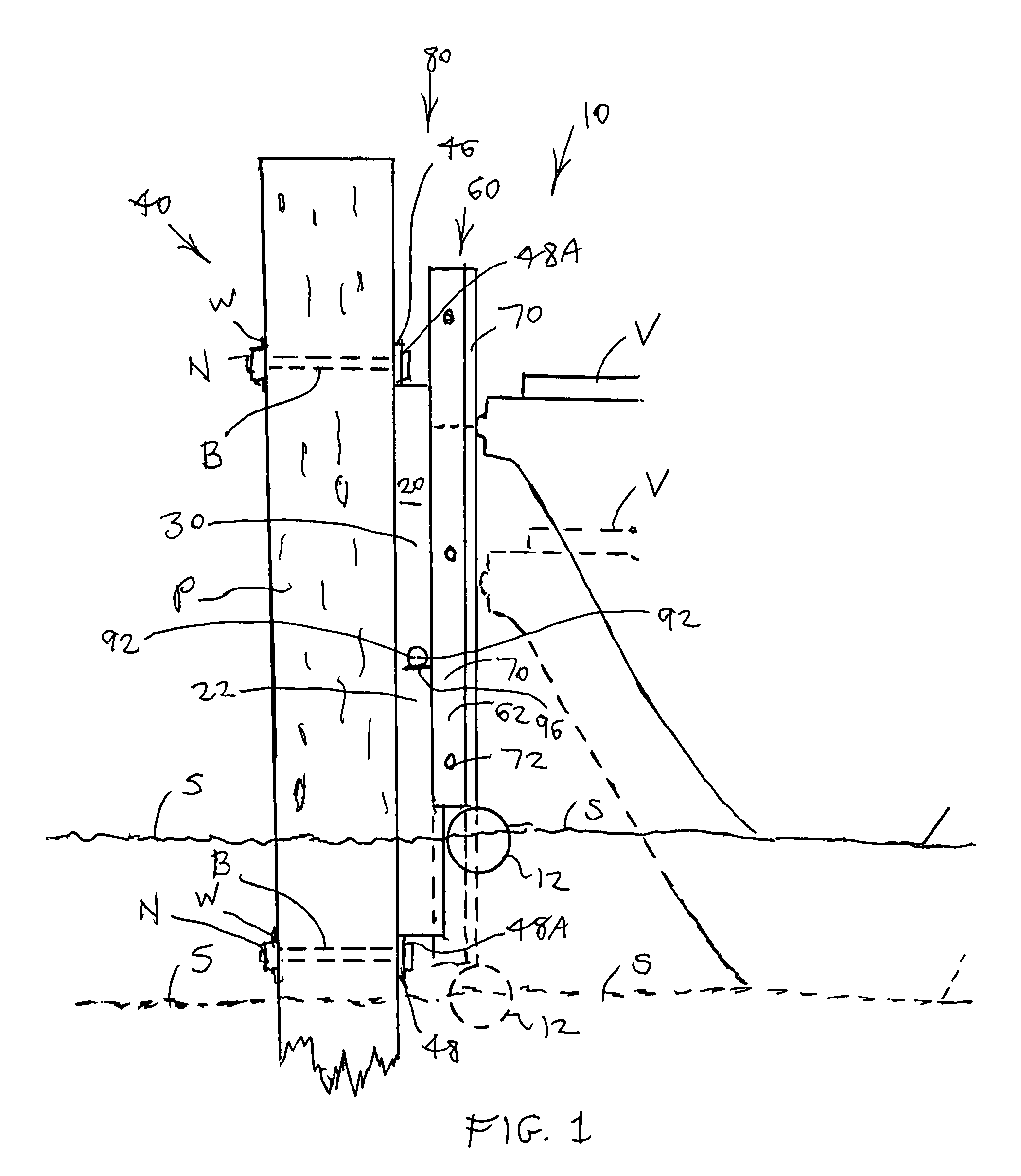
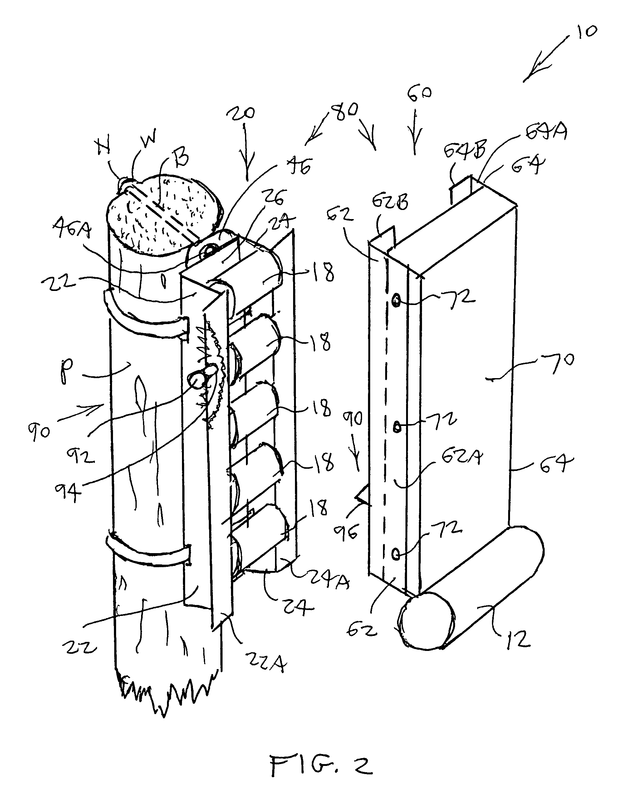
[0024]Referring to FIGS. 1-3, a buoyant bumper apparatus 10 is disclosed for mounting to a dock structure such as a piling P apparatus 10 having a bumper assembly 60 which buoyantly rises and falls with the tide and thus with any adjacent moored water vessel V such as a boat so that the bumper assembly 40 is always positioned between the piling P and the contacting portion of the vessel V. The bumper apparatus 10 includes stationary guide structure in the form of a roller rack 20 for mounting vertically along a piling P with rack fasteners 40, and bumper assembly 60 having a float 12 at its lower end and slidably engaging the roller rack 20 through a rack engaging structure 80.

[0025]The roller rack 20 preferably includes a spaced apart upright pair of opposing first and second mounting rails 22 and 24 and a longitudinal series of horizontal cylindrical rollers 18 mounted on individual roller axles 16 extending between and connected to the first and second mounting rails 22 and 24 so...


PUM


Abstract

A bumper apparatus includes a roller rack and rack fasteners for mounting the roller rack vertically along a dock structure; a bumper assembly having a buoyant structure having sufficient buoyancy to cause the bumper assembly to rise and fall with the water surface and thus with the tide and with any adjacent water vessel; and a rack engaging structure slidably interconnecting the roller rack and the bumper assembly so that the bumper assembly is slidable vertically relative to the roller rack. The roller rack preferably includes a spaced apart upright pair of opposing first and second mounting rails; and a longitudinal series of substantially horizontal cylindrical rollers mounted on individual roller axles extending between and connected to the first and second mounting rails so that the rollers protrude forwardly from the mounting rails.

Description

BACKGROUND OF THE INVENTION[0001]1. Field of the Invention[0002]The present invention relates generally to the field of boat and dock equipment. More specifically the present invention relates to a buoyant bumper apparatus for mounting to a piling such as along a dock, the apparatus having a bumper assembly which buoyantly rises and falls with the tide and thus with any adjacent water vessel such as a boat so that the bumper is always positioned between the piling and the contacting portion of the vessel. The bumper apparatus includes a roller rack for mounting vertically along a piling with rack fasteners, and a shock absorbing bumper assembly having a float at its lower end and slidably engaging the roller rack with a rack engaging structure.[0003]The roller rack preferably includes a spaced apart upright pair of opposing first and second mounting rails and a longitudinal series of horizontal cylindrical rollers mounted on individual roller axles extending between and connected to...

Claims


Application Information

Patent Timeline
Patent Type & Authority Patents(United States)
IPC IPC(8): B63B21/00
CPCE02B3/26Y02A30/30
Inventor KATULKA, MICHAEL A.
Owner KATULKA MICHAEL A
Why Eureka
Try Eureka