Pinch prevention structure of slide door

a technology of preventing structure and sliding door, which is applied in the direction of motor/generator/converter stopper, dynamo-electric converter control, roof, etc., can solve the problem of not disclosing any effective measures to prevent foreign matter pinching properly

Inactive Publication Date: 2011-10-04
MAZDA MOTOR CORP
View PDF8 Cites 23 Cited by
  • Summary
  • Abstract
  • Description
  • Claims
  • Application Information

AI Technical Summary

Benefits of technology

[0005]The present invention has been devised in view of the above-described problem, and an object of the present invention is to provide a pinch prevention structure of a slide door that can prevent any foreign matter from being pinched in the gap formed between the slide door and the rear edge portion of the side opening when the slide door is moved from the closed position toward the open position.
[0006]According to the present invention, there is provided a pinch prevention structure of a slide door, comprising a slide door provided to be movable between a closed position in which the slide door covers a side opening formed at a vehicle-body side face and an open position in which the slide door opens the side opening, the slide door being configured to move outward and subsequently slide rearward along a rear vehicle-body outer face when the slide door moves from the closed position to the open position, a drive device operative to drive the slide door so as to move between the closed position and the open position, a drive control device operative to control the drive device, and a detection sensor operative to detect a foreign matter in coming into a gap from a vehicle-compartment inside, which is formed between an inner side face of the slide door and a rear edge portion of the side opening when the slide door is moved from the closed position toward the open position, wherein the drive control device is configured so that a drive of the slide door by the drive device is stopped in case the detection sensor detects the foreign matter in coming into the gap when the drive device drives the slide door in the closed position toward the open position. According to the present invention, when the foreign matter is about to come into the gap from the vehicle inside, the detection sensor detects such foreign matter and thereby the drive of the slide door toward the open position is stopped. Thereby, any foreign matter can be prevented from being pinched in the gap properly.
[0007]According to an embodiment of the present invention, the rear edge portion of the side opening includes a rear-edge front face portion that faces forward and a rear-edge side face portion that extends forward from an inside end of the rear-edge front face portion, the rear-edge front face portion and the rear-edge side face portion forming an open edge portion that is recessed toward the vehicle inside, at the open edge portion is provided a cover member that is operative to extend in a vehicle width direction so as to cover part of the gap formed when the slide door is moved from the closed position toward the open position, and the detection sensor is configured to detect the foreign matter in contacting the cover member in an operative position from the front. Thereby, since the cover member is located at the operative position so as to cover part of the gap when the slide door is moved from the closed position toward the open position, it can be surely prevented that any object (foreign matter) located inside the vehicle from coming into the gap. Further, the cover member itself can be utilized as means for detecting any foreign matter. Also, since the cover member is disposed by properly using a space of the recessed open edge portion that is recessed, there may be no need to provide any particular layout space for the cover member.

Problems solved by technology

The above-described publications just disclose the foreign-matter pinch detection itself, but not disclose any effective measures to prevent the foreign-matter pinch properly.

Method used


Image

  • Pinch prevention structure of slide door
  • Pinch prevention structure of slide door
  • Pinch prevention structure of slide door

Examples


embodiment 1

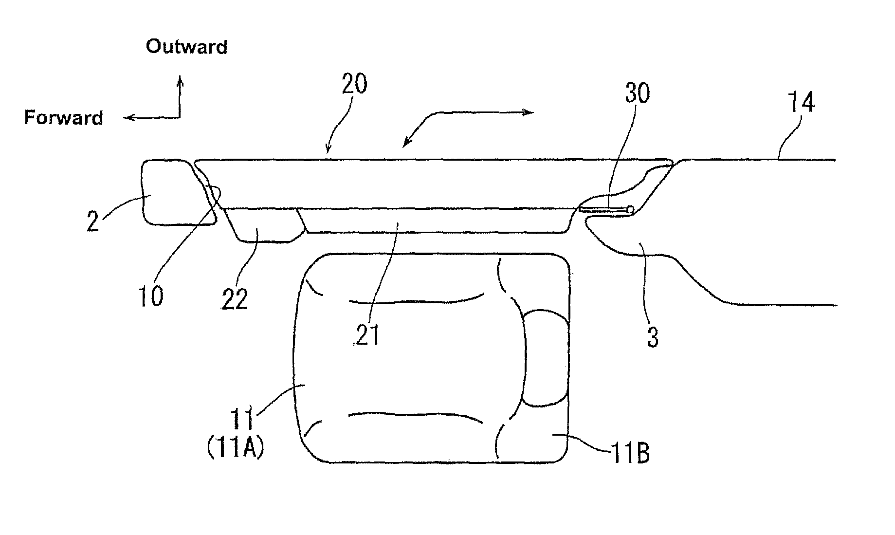
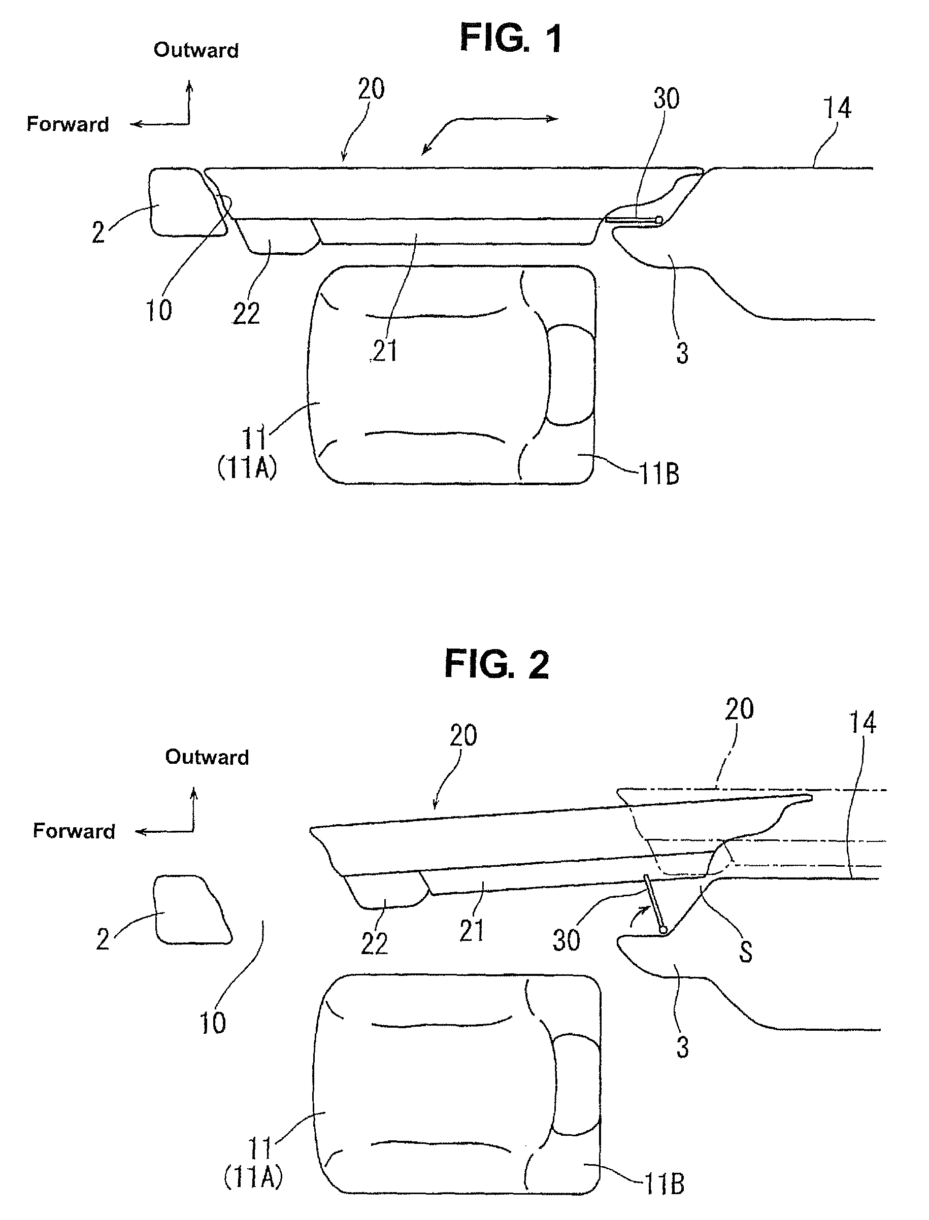
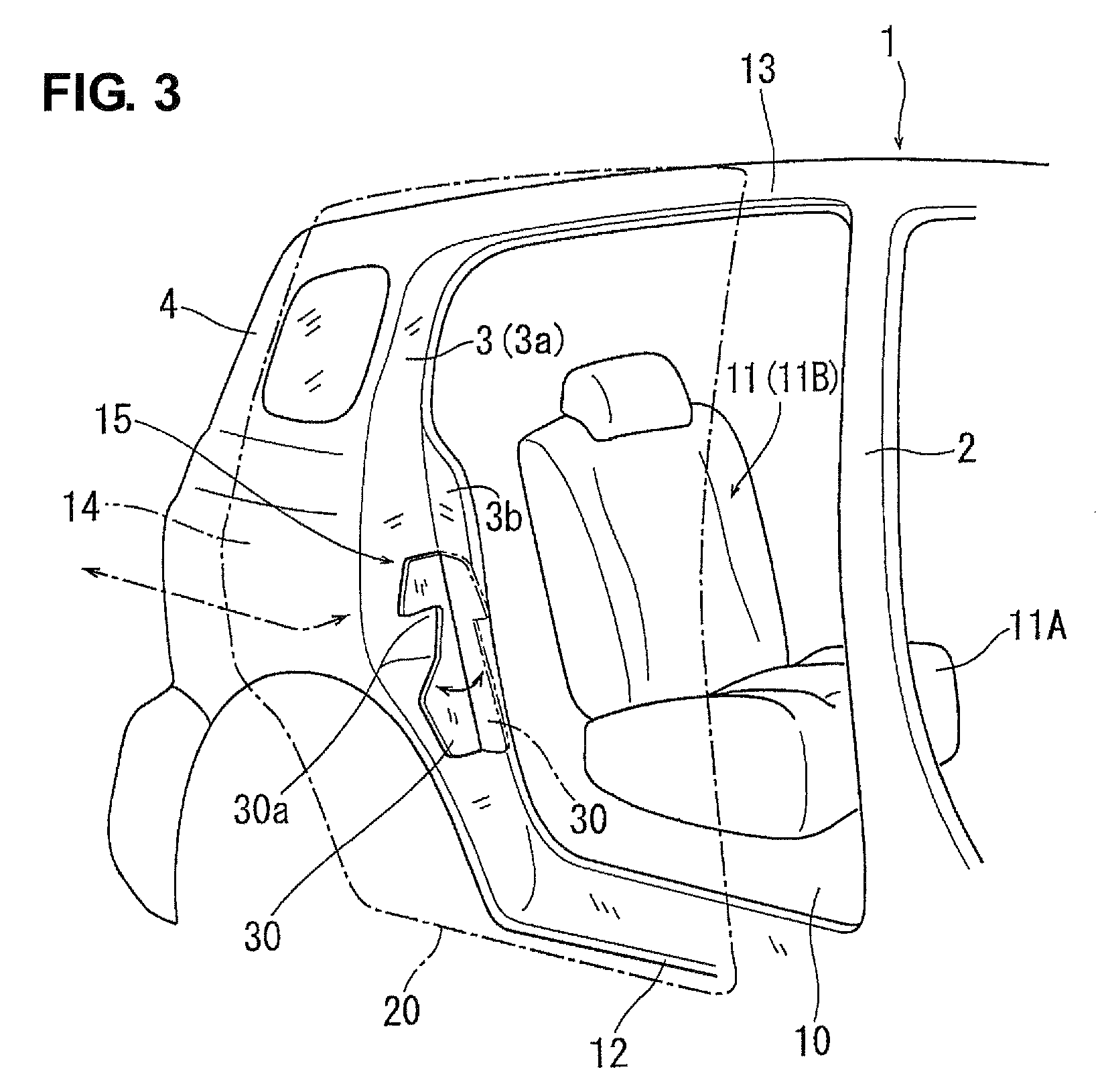
[0033]In FIGS. 1 through 4, reference character 1 denotes a vehicle body, 2 denotes a B pillar (center pillar), 3 denotes a C pillar that is located right behind the B pillar 2, and 4 denotes a rearmost D pillar that is located behind the C pillar 3.

[0034]As apparent from FIG. 3 particularly, a side opening 10 is formed at a vehicle-body side face between the B pillar 2 and the C pillar 3. A front edge portion of the side opening 10, which is for ingress and egress of a passenger for a rear seat (second-row seat) 11, is comprised of the B pillar 2, its rear edge portion is comprised of the C pillar 3, its lower edge portion is comprised of a side sill 12, and its upper edge portion is comprised of a roof side rail (outer end portion of a roof panel) 13.

[0035]The side opening 10 is opened and closed by a slide door 20. That is, the slide door 20 is configured to take a closed position in which the side opening 10 is closed by it (a state shown in FIG. 1) and an open position in which...

embodiment 2

[0053]FIGS. 13 and 14 show a second embodiment of the present invention. Herein, the same structure elements as those in the above-described first embodiment are denoted by the same reference characters, and duplicated descriptions on those are omitted here. In the present embodiment, the pressure sensitive switch 50 is attached to the rear-edge side face portion 3b of the open edge portion 15. That is, as shown in FIG. 14, the holding bracket 40 is fixed to the rear-edge side face portion 3b, and the casing 51 of the pressure sensitive switch 50 is fixed to the holding bracket 40. The contact 52 of the pressure sensitive switch 50 faces outward. Herein the contact 52 (its tip portion) is sealed from the outside with a seal member 56.

[0054]Meanwhile, a pressing portion 30c is formed at the cover member 30 so as to project from a portion of the cover member 30 that is located near its rotational center and at a level that corresponds to the disposition level of the holding bracket 40...

embodiment 3

[0056]FIGS. 15 through 17 show a third embodiment of the present invention. Herein, the same structure elements as those in the above-described first embodiment are denoted by the same reference characters, and duplicated descriptions on those are omitted here. In the present, a stopper portion 40b is formed at the holding bracket 40 so as to project downward, which prevents the cover member 30 from rotating beyond a specified range. The lower holding bracket 40 has also this stopper portion 40b. Thus, the prevention of the cover member 30 beyond the specified range can be achieved surely by the both stopper portions 40b.

[0057]The present invention should not be limited to the above-described embodiments, and any other modifications may be applied within the scope of a sprit of the present invention. For example, the cover member 30 may be comprised of vertically-split parts. In this case, the gap S may be preferably covered in a properly wide range in the vehicle width direction, ...


PUM


Abstract

A slide door is provided to be movable between a closed position to cover a side opening formed at a vehicle-body side face and an open position. The slide door is configured to move outward and subsequently slide rearward along a rear vehicle-body outer face when the slide door moves from the closed position to the open position. There is provided a detection sensor to detect a foreign matter in coming into a gap from a vehicle-compartment inside. A drive of the slide door is stopped in case the detection sensor detects the foreign matter in coming into the gap when the slide door moves toward the open position. Thereby, any foreign matter can be prevented from being pinched in the gap formed between the slide door and the rear edge portion of the side opening.

Description

BACKGROUND OF THE INVENTION[0001]The present invention relates to a pinch prevention structure of a slide door.[0002]A vehicle, such as a so-called one-box type of automotive vehicle, is equipped with a slide door that is provided to open and close a side opening formed at a vehicle-body side face, through which a passenger gets onto or gets off from a rear seat. The slide door is generally configured to move outward and subsequently slide rearward along a rear vehicle-body outer face when the slide door moves from its closed position to its open position. The slide door may be driven by an electric motor.[0003]Herein, when the slide door is moved from the closed position to the open position, a gap is formed between an inner side face of the slide door and a rear edge portion of the side opening. Japanese Patent Laid-Open Publication No. 2007-56522 discloses a pressure sensitive sensor that is provided at the inner side face of the slide door to detect a load that occurs in a vehic...

Claims


Application Information

Patent Timeline
Patent Type & Authority Patents(United States)
IPC IPC(8): E05F5/02
CPCE05F15/48E06B7/36E05Y2201/11E05Y2600/45E05Y2900/531Y10T16/61E05F15/646E05F2015/483
Inventor NAKAURA, MASAKITANAKA, KAZUHIROSATO, YUZO JPKUSU, HIROTAKA
Owner MAZDA MOTOR CORP
Why Eureka
Try Eureka