Moisture condensation control system

a technology of moisture condensation and control system, which is applied in the direction of drying machines, air heaters, machines/engines, etc., can solve the problems of condensation on the surface, loss of moisture holding ability, mold, etc., and achieve the effect of efficient removal

Inactive Publication Date: 2011-10-04
AQUALIZER
View PDF603 Cites 15 Cited by
  • Summary
  • Abstract
  • Description
  • Claims
  • Application Information

AI Technical Summary

Benefits of technology

[0009]The present invention is directed to a moisture condensation control system that can be incorporated into a structure to control moisture condensation on the structure's inside and outside surface(s). As used herein, the term structure refers to a anything that may be used for shelter such as for example and without limitation buildings, houses, garages, warehouses, barns, sheds, caves, cellars, treehouses, hangars, factories, sports arenas, natatoriums, greenhouses and the like. Such control may include minimizing the amount of condensation that occurs as well as where the condensation occurs. The illustrative moisture control device may induce or encourage condensation on a particular surface and thereby retard condensation on other surfaces of the structure.
[0012]The moisture control device provides an apparatus and method for passively inducing vapor pressure drives toward the collector element, and water condensation on the surface(s) thereof. The collector element blocks the fluid flow and starts condensing water on its surface. If the ambient temperature of the collector surface is above the freezing point of water, then the condensed water begins draining or rolling off of the surface as soon as the water layer thickness on the collector surface becomes great enough to overcome surface tension. If the ambient temperature of the collector surface is below the freezing point of water, then the condensed water is stored on the collector surface as frost and ice, which will melt and roll off the surface as soon as the surface temperature rises above freezing. The condensed water rolls off of the surface(s) and into the water collection reservoir. The channel transports the collected water away from the moisture control device. The operation of the moisture control device reduces the amount of water that would otherwise accumulate in the porous construction materials or condensate on the structure's surfaces thereby resulting in mold growth, rot, corrosion, structural loss of strength, degradation in materials, increases in energy loss and the like.
[0014]It may be desirable to have an airgap between the collector's surface(s) and any covering material positioned in front of the collector's surface(s). As noted, such material may include a wall, sheathing, insulation, a curtain, a cover, and the like. The thickness of such an airgap may range from about 2.5 mm to about 9.5 mm. Tests have shown that fluid is more efficiently removed by the collector element if the airgap is between about 8.5 mm to about 9.5 mm, preferably about 9.0 mm.

Problems solved by technology

When the humidity inside a structure is greater than 50%, condensation of the water vapor can occur, leading to mold, rot, pest infestation, and the like.
When air cools, it loses its ability to “hold” moisture.
Sinks that attract water vapor include surfaces having a temperature that chills the air coming in contact with the surface to the dew point, thereby causing condensation on the surface.
Thus, whether the fluid is infiltrating from outside to inside, as on a relatively hot day, or exfiltrating from inside to outside, as on a relatively cold day, condensation may occur on the window(s) and may drip down into the sill, causing damage to the structure.
For example, when conventional window frames and sashes are used in structures in which the temperature inside the structure is greater than the temperature outside the structure, heat transfer from portions of the frame and sash inside the structure may lower the temperature of those portions below the dew point of the air inside the structure, thereby causing moisture condensation on their inside surfaces.
Conversely, if the temperature outside the structure is greater than the temperature inside the structure, then the heat transfer may lower the dew point of the air outside the structure, thereby causing moisture condensation on the outside surfaces.
Such condensation may facilitate the formation of mold or otherwise cause damage to the structure.
Such barriers are not only sometimes difficult to install properly, but do not always sufficiently minimize the heat transfer from the inside frame portions to prevent moisture condensation thereon.
However, a dehumidifier typically requires some type of electrical power to extract the water vapor from the air.

Method used


Image

  • Moisture condensation control system
  • Moisture condensation control system
  • Moisture condensation control system

Examples


Embodiment Construction

[0020]For the purposes of promoting an understanding of the principles of the invention, reference will now be made to a number of illustrative embodiments illustrated in the drawings and specific language will be used to describe the same.

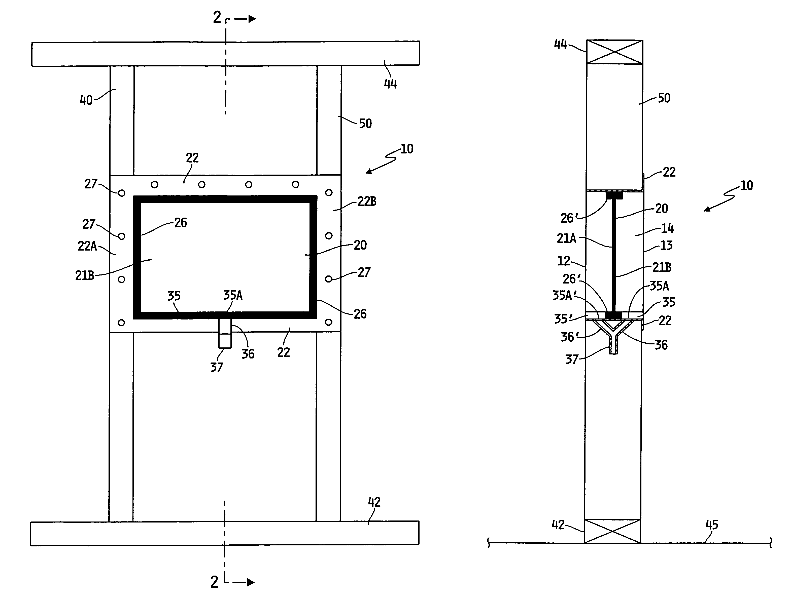
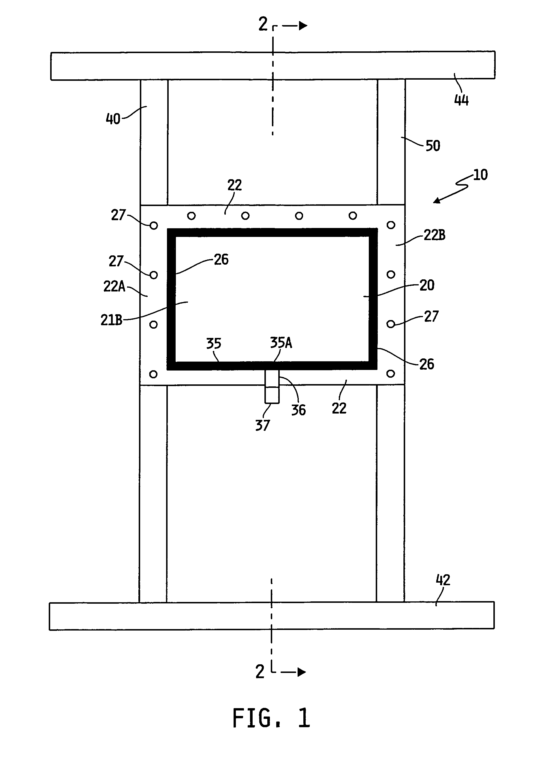
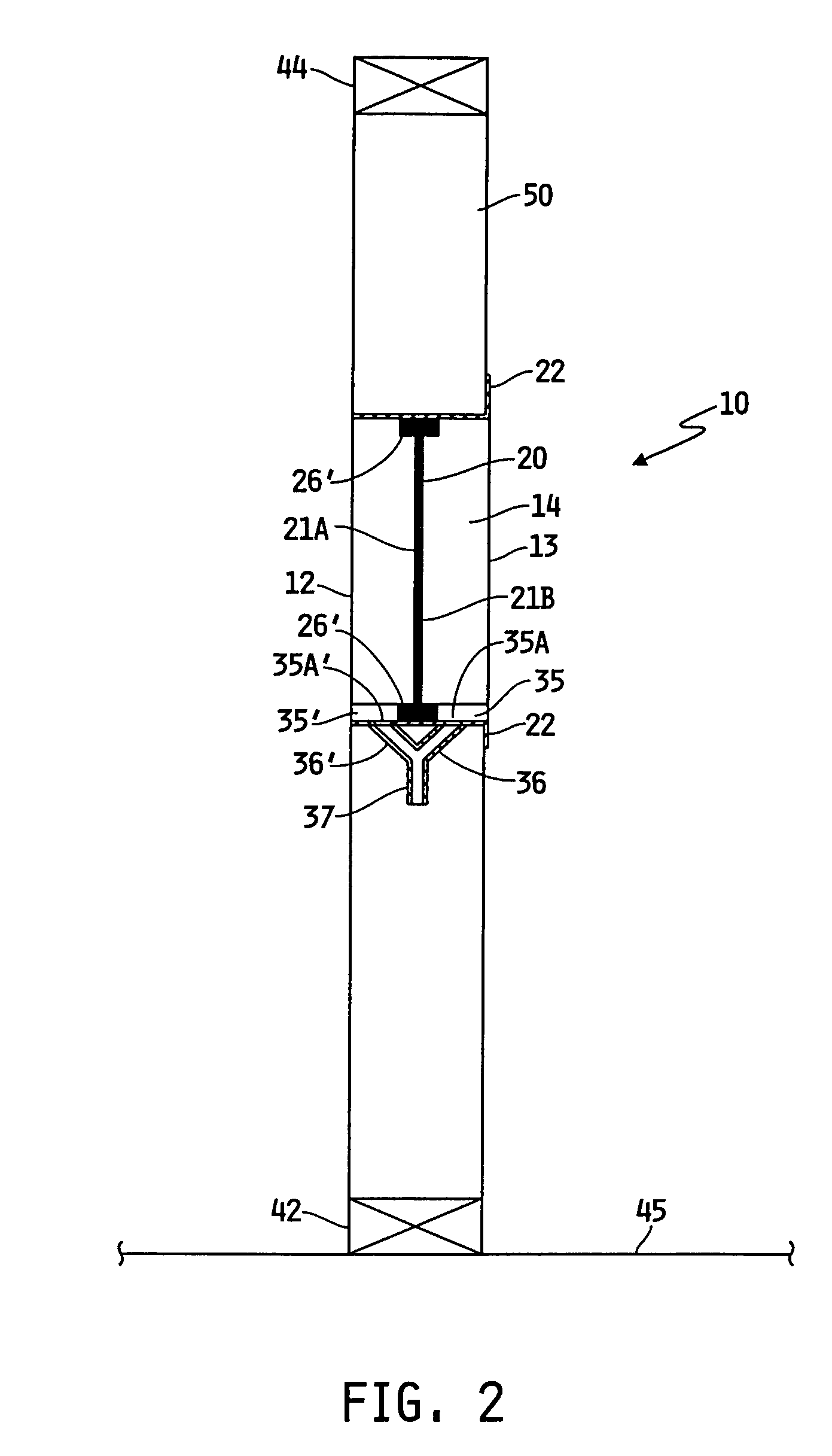
[0021]FIGS. 1-2 illustrate a preferred embodiment of a moisture condensation control system or device 10. The moisture condensation control system 10 can be incorporated into any suitable structural component or portion of a structure including for example and without limitation a door, a wall, a ceiling, a floor, a window, the basement, or the roof of the structure in order to control moisture condensation on and within the structure.

[0022]In the illustrative case where the control system 10 is installed or attached to the wall of a structure, the structure's stud wall section or frame generally includes a base stud plate 42 extending along and secured to, the floor joist(s) 45 of the structure and a plurality of studs that extend vertically betw...


PUM

PropertyMeasurementUnit
humidityaaaaaaaaaa
thicknessaaaaaaaaaa
metallicaaaaaaaaaa

Abstract

A moisture control system generally comprising a collector element is configured to be incorporated into a structure to control moisture condensation on the interior and exterior of the structure. The collector element encourages condensation on its surface. The control system includes a channel in fluid communication with the collector element to direct the condensed liquid away from the control element.

Description

RELATED APPLICATIONS[0001]This application is a U.S. national counterpart application under 37 C.F.R. §371(b) of PCT international application serial no. PCT / US2005 / 023112 filed Jun. 30, 2005, which claims the benefit of and priority to U.S. Provisional Application No. 60 / 584,888, filed Jul. 2, 2004.FIELD OF THE INVENTION[0002]The present invention relates generally to the control of moisture in a structure, and more specifically to the minimization of moisture condensation on the inside of a structure.BACKGROUND OF THE INVENTION[0003]Moisture may collect in the cavities of structures, such as for example and without limitation houses, buildings and the like. This moisture may come from capillary transport, such as by wind-driven rain, by rain or other water leaking into the structure, by water vapor diffusion and fluid flows, such as airflow, through the wall(s) of the structure. As used herein, the term fluid refers generally to any substance tending to flow or conform to the outl...

Claims


Application Information

Patent Timeline
Patent Type & Authority Patents(United States)
IPC IPC(8): F26B25/00
CPCF24F13/222F26B21/086Y10T137/3105
Inventor PEDTKE, WILLIAM SCOTT
Owner AQUALIZER
Why Eureka
Try Eureka