Diesel engine charge air cooler bypass passage and method

a technology of bypassing passage and bypassing air cooler, which is applied in the direction of machines/engines, mechanical equipment, and non-fuel substance addition to fuel, etc., can solve the problems of excessive carbon deposits on the egr valve and intake sensor, undesirable white smoke and odors, and difficult optimization of engine operation at idle, etc., to reduce the condensation of hydrocarbons

Active Publication Date: 2007-08-21
INT ENGINE INTPROP CO LLC
View PDF21 Cites 46 Cited by
  • Summary
  • Abstract
  • Description
  • Claims
  • Application Information

AI Technical Summary

Benefits of technology

[0007]The following describes an apparatus for and method of bypassing a charge air cooler in a turbocharged diesel internal combustion engine. The diesel engine may have an intake throttle device, and may additionally have one or more turbochargers. A bypass air passage having a fixed orifice may be used to bypass the charge air cooler and the intake throttle. The bypass air passage is connected between a first location upstream of the charge air cooler and a second location downstream of the intake throttle valve. If an EGR system is employed, the bypass air path may be connected upstream of the EGR valve and may advantageously be directed toward an outlet of the EGR system. Warm air from the bypass passage directed toward the outlet of the EGR system may advantageously reduce condensation of hydrocarbons at a point of introduction of EGR gas, and help mixing of intake air and exhaust gas.

Problems solved by technology

For a compression ignition engine having at least one turbocharger and an intake air cooler, operation of the engine at or around idle is difficult to optimize for various reasons.
First, because low temperature air flows into the engine through the intake charge air cooler, under low ambient temperatures, the air entering the intake manifold may be over-cooled and, when an exhaust gas recirculation (EGR) system is utilized, cause excessive carbon deposits on the EGR valve and intake sensors.
Second, low intake air temperatures at engine idle conditions may result in undesirable white smoke and odors in the exhaust of compression ignition engines due to incomplete combustion of the fuel.
The bypass air capacity of this bypass system is only capable of handling a relatively small amount of air flow, adequate for engine idle.
An idling speed control system, such as shown in Nakao et al. is expensive and complicated because it not only requires an actuator, but it also requires structure for controlling the amount of air allowed to enter the engine because the amount of air entering the engine determines the speed of the engine.

Method used


Image

  • Diesel engine charge air cooler bypass passage and method
  • Diesel engine charge air cooler bypass passage and method
  • Diesel engine charge air cooler bypass passage and method

Examples


Embodiment Construction

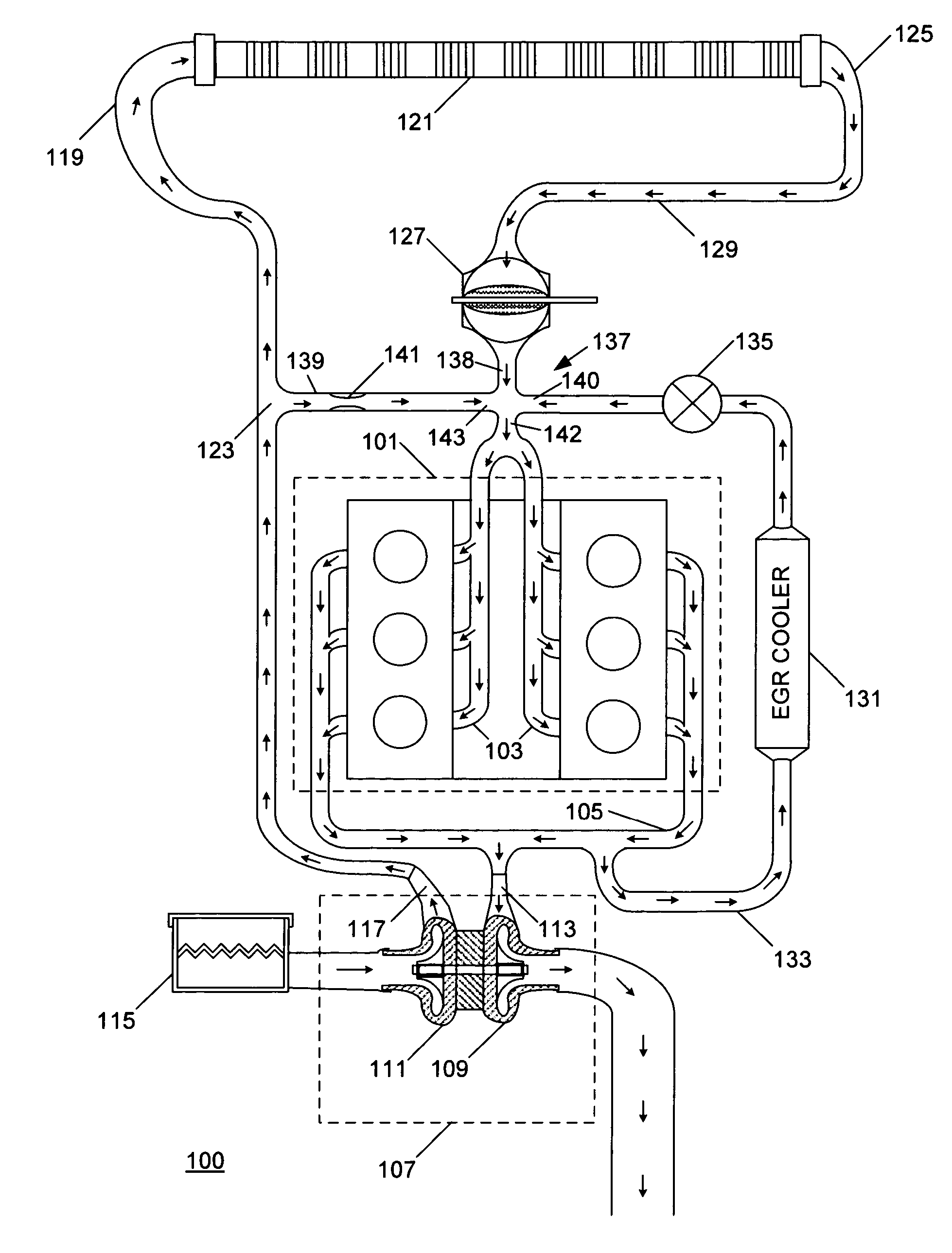
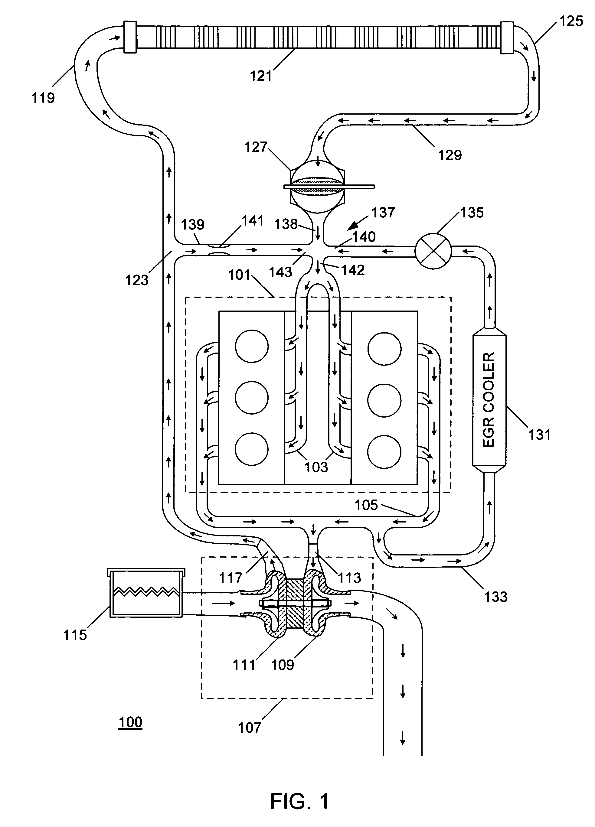
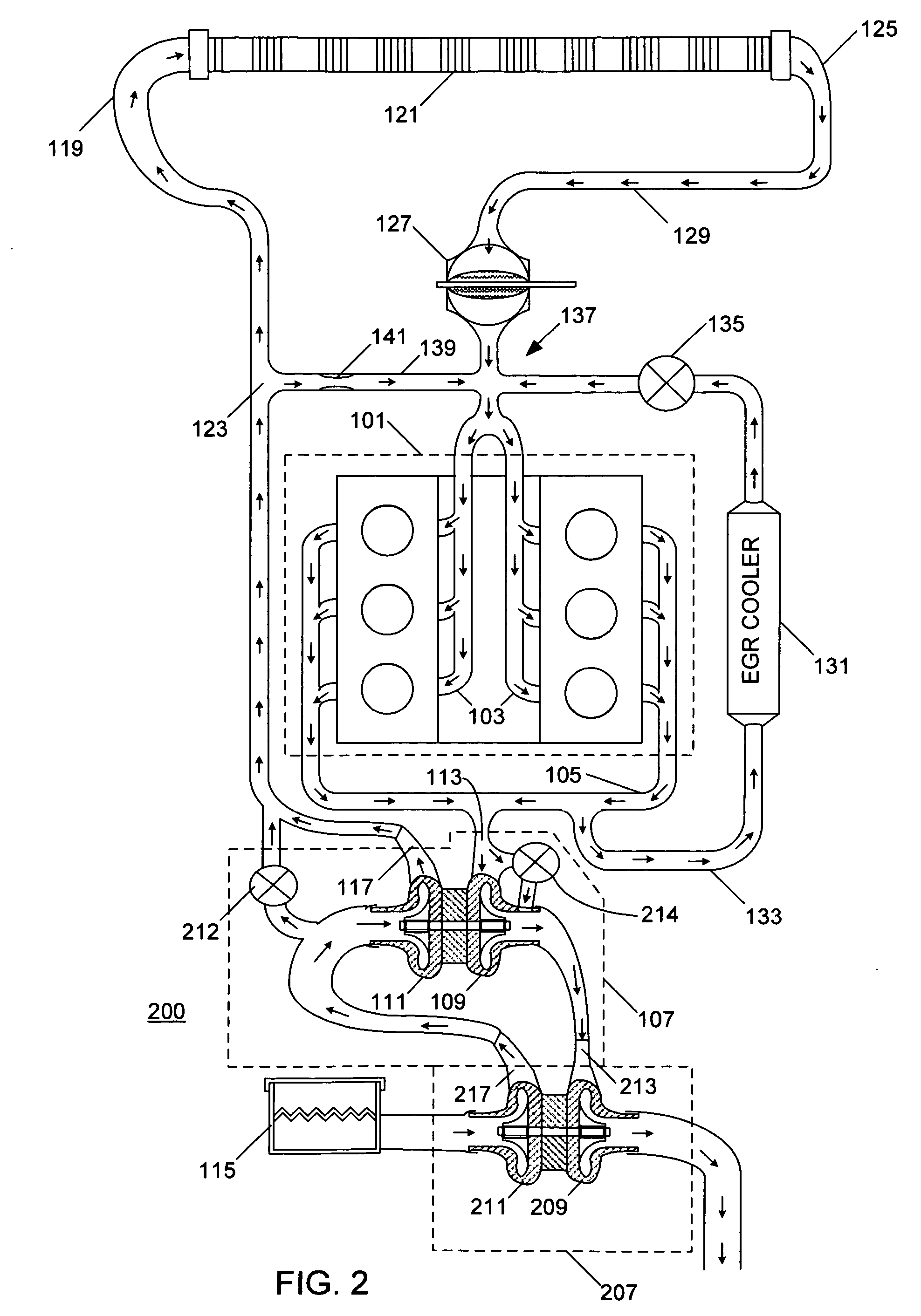
[0016]The following describes an apparatus for and method of bypassing a charge air cooler in a turbocharged diesel engine. The diesel engine may have an intake throttle device, and may additionally have one or more turbochargers. A bypass air passage having a fixed orifice may be used to bypass the charge air cooler. The bypass air passage is connected between a first location upstream of the charge air cooler and a second location downstream of the intake throttle valve. If EGR is employed, the bypass air path may be connected upstream of the EGR and may advantageously be directed at an outlet of the EGR system. Warm air from the bypass passage directed toward the outlet of the EGR system may advantageously reduce condensation of hydrocarbons at a point of introduction of EGR gas, and help mixing of intake air and exhaust gas.

[0017]A diesel engine 100 is shown in FIG. 1. The engine 100 has a crankcase 101 that includes a plurality of cylinders. The cylinders in the crankcase 101 a...


PUM


Abstract

An internal combustion engine (100) includes a turbocharger (107) having a turbine (109) and a compressor (111). A charge-air cooler (121) is in fluid communication with an outlet (117) of the compressor (111) through a hot-air passage (123). An intake throttle (127) is in fluid communication with an outlet (125) of the charge-air cooler (121) through a cool-air passage (129). A junction (137) is located downstream of the intake throttle (127). An intake system (103) and an exhaust gas recirculation system (131, 133, 135) are in fluid communication with the junction (137). A bypass passage (139) containing an orifice (141) fluidly connects the hot-air passage (123) and the intake system (103).

Description

FIELD OF THE INVENTION[0001]This invention relates to intake air conditioning for internal combustion engines, including but not limited to intake air conditioning for engines having at least one turbocharger and an intake air cooler.BACKGROUND OF THE INVENTION[0002]Internal combustion engines having intake air coolers are known. Typical engines having turbochargers use intake air coolers between compressors, or between a compressor and an intake manifold. Intake air coolers lower the temperature of incoming air to the engine cylinders. Typically, air passes through an air filter before entering a compressor or a supercharger. The compressor compresses the air, resulting in the air exiting the compressor being at a higher pressure and temperature than air entering the compressor.[0003]Compressed air is either sent directly to the intake manifold of the engine, or cooled in an intake air or charge air cooler disposed between the compressor and the intake manifold. Cooling the air is ...

Claims


Application Information

Patent Timeline
Patent Type & Authority Patents(United States)
IPC IPC(8): F02B33/44F02B29/04F02M25/07
CPCF02B29/0418F02B37/013F02B37/16F02B37/18F02D23/02F02B37/004F02B3/06F02M25/0707F02M25/0711F02M25/0727F02M25/0749Y02T10/146Y02T10/144F02M26/43F02M26/05F02M26/08F02M26/23Y02T10/12
Inventor IWASZKIEWICZ, TITUS J.
Owner INT ENGINE INTPROP CO LLC
Why Eureka
Try Eureka