Humidity reducing exhaust duct for dishwasher

a technology of exhaust duct and dishwasher, which is applied in the field of automatic dishwashing machines, can solve the problems of reducing drying efficiency, affecting the drying efficiency of the dish, so as to reduce the humidity, reduce the amount of water collected, and minimize the effect of condensation problems

Active Publication Date: 2008-10-30
ILLINOIS TOOL WORKS INC
View PDF14 Cites 50 Cited by
  • Summary
  • Abstract
  • Description
  • Claims
  • Application Information

AI Technical Summary

Benefits of technology

[0006]The present invention provides an improved vent system for a dishwasher that may accommodate high humidity air such as produced by downdraft venting systems. The vent provides a mixing chamber that mixes the humid air from the washing chamber with drier outside air ...

Problems solved by technology

The sealed nature of this chamber makes the promotion of air circulation for proper venting particularly difficult.
The greater efficiency of this design in removing moisture from the wash cavity and contained dishes can create cond...

Method used


Image

  • Humidity reducing exhaust duct for dishwasher
  • Humidity reducing exhaust duct for dishwasher
  • Humidity reducing exhaust duct for dishwasher

Examples


Embodiment Construction

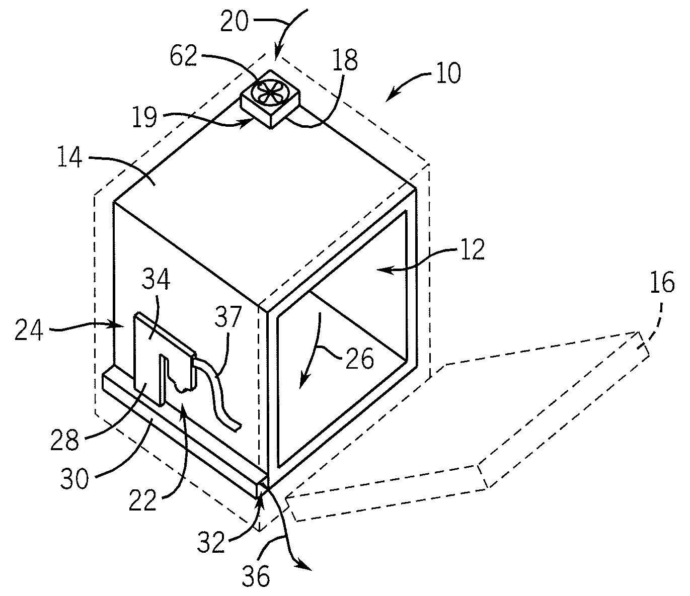
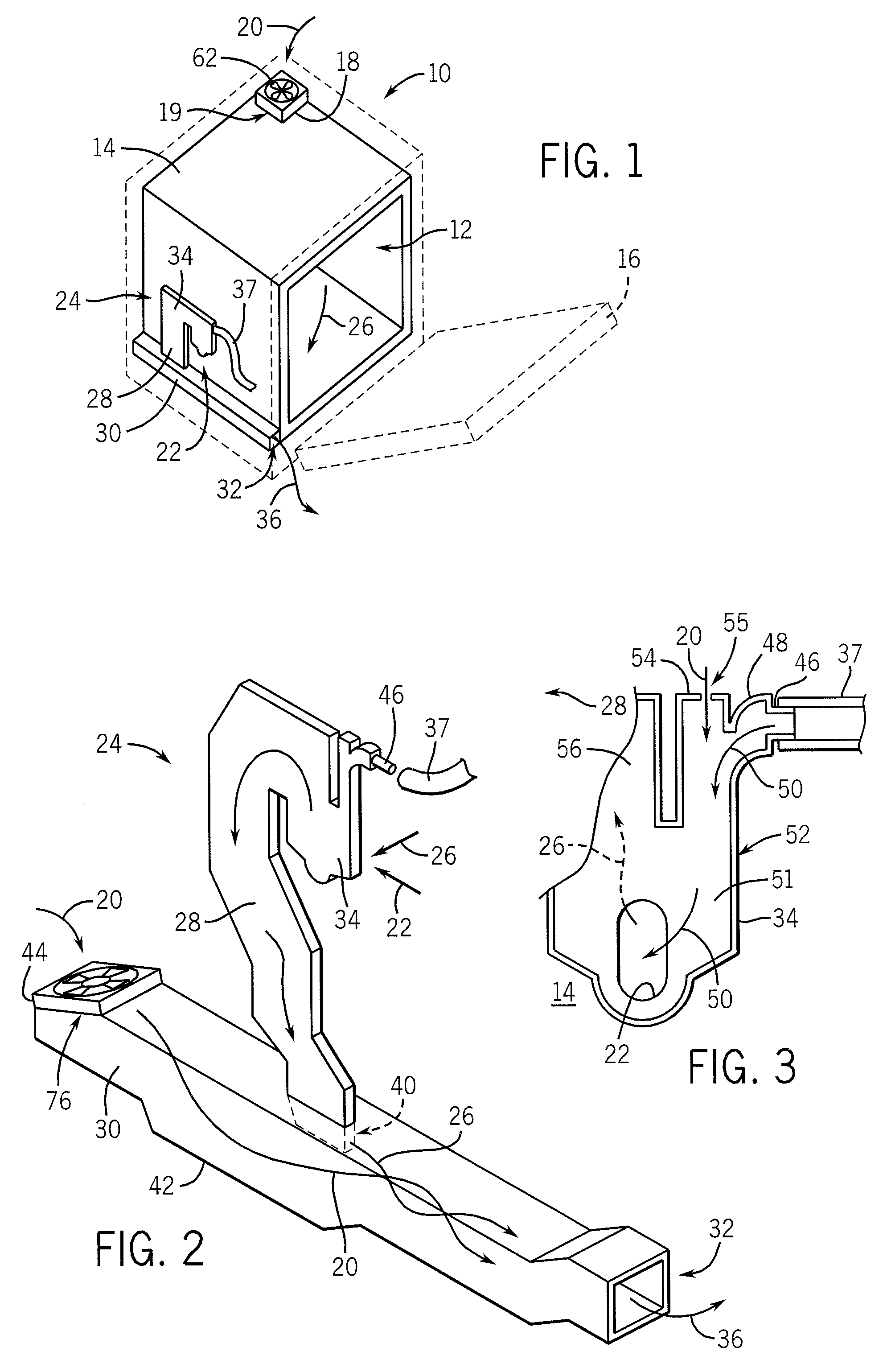
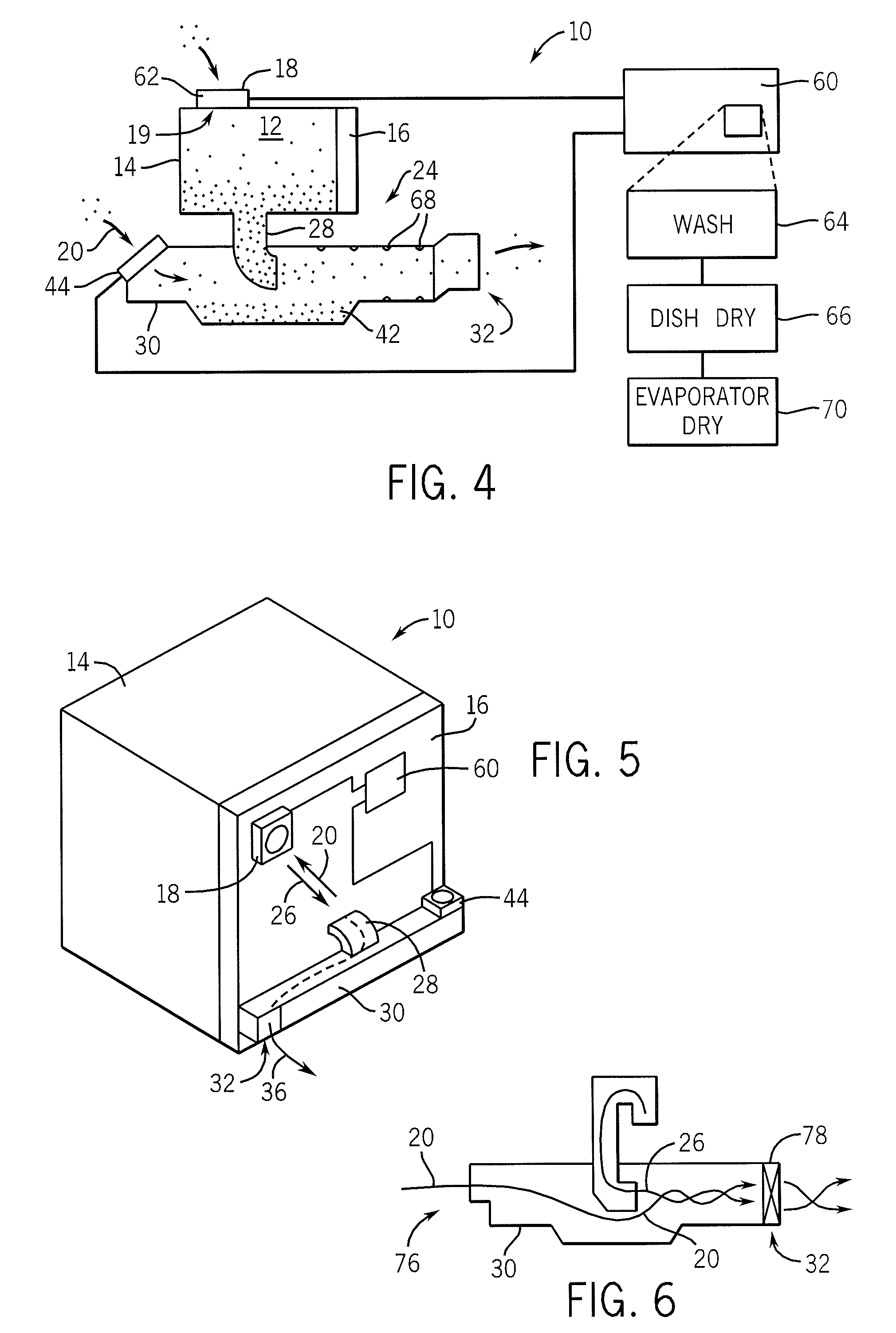
[0035]Referring now to FIG. 1, a dishwasher 10 may include a wash cavity 12 into which dishes and cutlery may be placed for washing on racks (not shown). The wash cavity 12 may be defined by a generally rectangular tub 14, for example, of drawn stainless steel, providing a single piece sealable volume open at the front to be covered by a door 16 that seals against a front lip of the tub 14.

[0036]An opening 19 may be cut in the tub 14, for example, at a right rear edge of the top of the tub 14, for the attachment of a vent unit 18. The vent unit 18 includes a fan and an electrically actuable door (not shown) operating together to allow dry air 20 from outside of the wash cavity 12 to be blown into the tub 14 to cause a downward evacuation of the humid air within the tub 14 at the conclusion of the washing cycle when drying of the dishes is desired. The fan in the vent unit 18 may be so-called “muffin fan” using a low voltage brushless DC motor with the door protecting the brushless D...


PUM


Abstract

A vent system for a dishwasher provides a mixing chamber receiving high humidity air from a downdraft dishwasher vent system or the like and mixes this air with dry air before discharging it from the dishwasher to reduce the humidity of the discharged air moderating condensation problems

Description

STATEMENT REGARDING FEDERALLY SPONSORED RESEARCH OR DEVELOPMENTCROSS REFERENCE TO RELATED APPLICATIONBACKGROUND OF THE INVENTION[0001]The present invention relates to automatic dishwashing machines (dishwashers) and in particular to a dishwasher providing improved dish drying.[0002]Dishwashers, such as those found in many homes, provide a wash cavity holding one or more racks into which eating utensils and cookware may be placed for cleaning. The wash cavity may be sealed by a door opening at the front of the wash cavity to allow loading and unloading of the chamber. The door is closed during a washing cycle to prevent the escape of water sprayed within the volume of the wash cavity and used to wash items placed in the racks. Upon completion of the washing cycle, a drying cycle is initiated during which water is drained from the wash cavity and moist air is discharged through a vent. Cool air, pulled by convection or a fan into the chamber through a lower vent, dries the heated dish...

Claims


Application Information

Patent Timeline
IPC IPC(8): B08B3/10
CPCA47L15/483A47L15/488A47L2401/20A47L2501/10A47L2501/12
Inventor BREWER, MARK EDWARDSTELZER, WALTER G.HAPKE, KENYON A.
Owner ILLINOIS TOOL WORKS INC
Why Eureka
Try Eureka