Scanning confocal microscope

a confocal microscope and scanning technology, applied in the field of scanning confocal microscopes, can solve the problems of unfavorable scanning site, undesirable temperature gradient between the incubator and the inverted microscope, and shifting of the examination site, so as to achieve the effect of reducing brightness

Inactive Publication Date: 2008-10-09
OLYMPUS CORP
View PDF3 Cites 54 Cited by
  • Summary
  • Abstract
  • Description
  • Claims
  • Application Information

AI Technical Summary

Benefits of technology

[0010]The present invention provides a scanning confocal microscope capable of providing an image of a specimen under examination using a

Problems solved by technology

Simply mounting the incubator on the stage of the inverted microscope, however, leaves a temperature difference between the incubator and the inverted microscope.
This causes an undesirable temperature gradient in the microscope and its scanning unit.
Such a temperature gradient in the optical components

Method used


Image

  • Scanning confocal microscope
  • Scanning confocal microscope
  • Scanning confocal microscope

Examples


Embodiment Construction

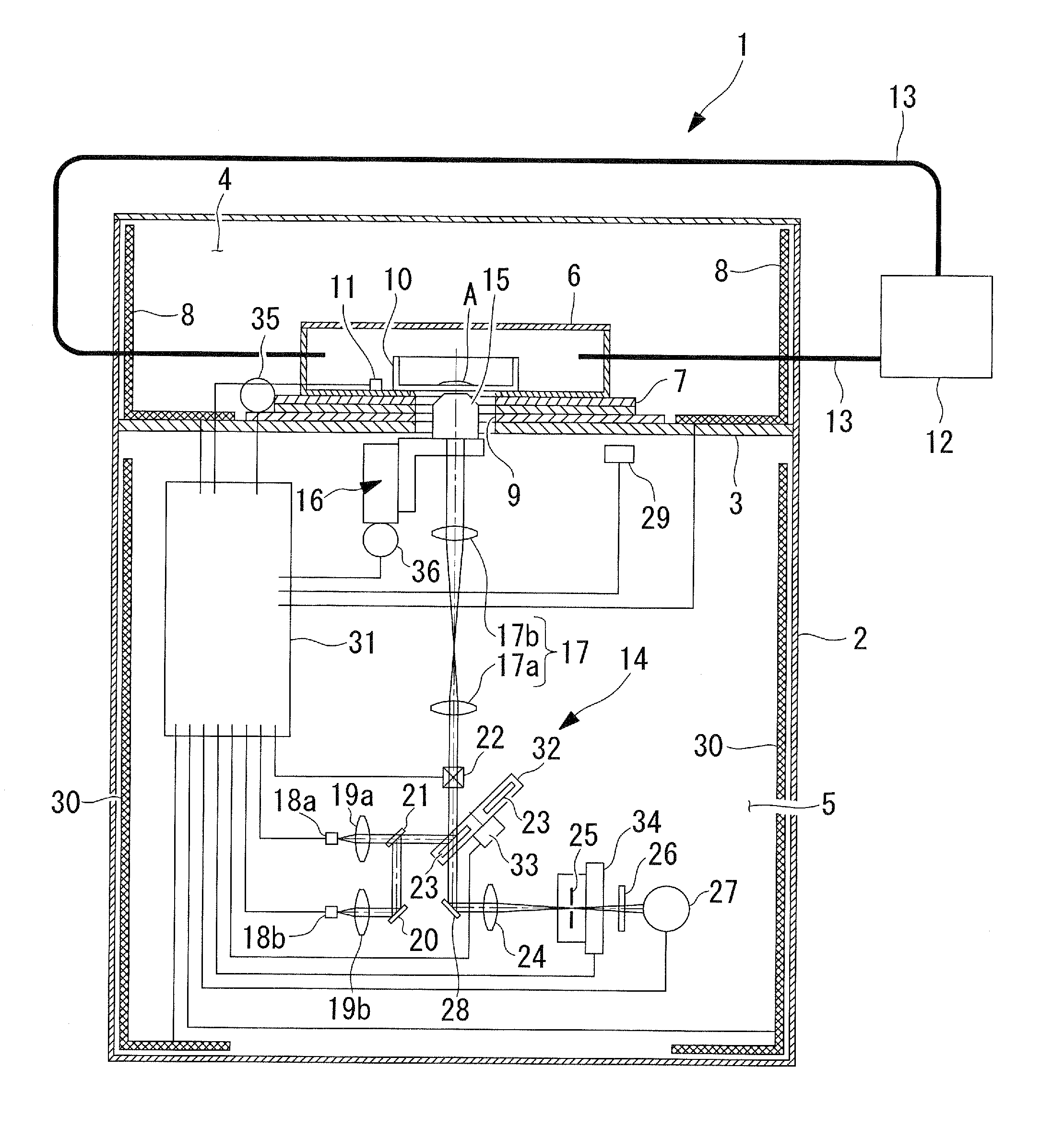
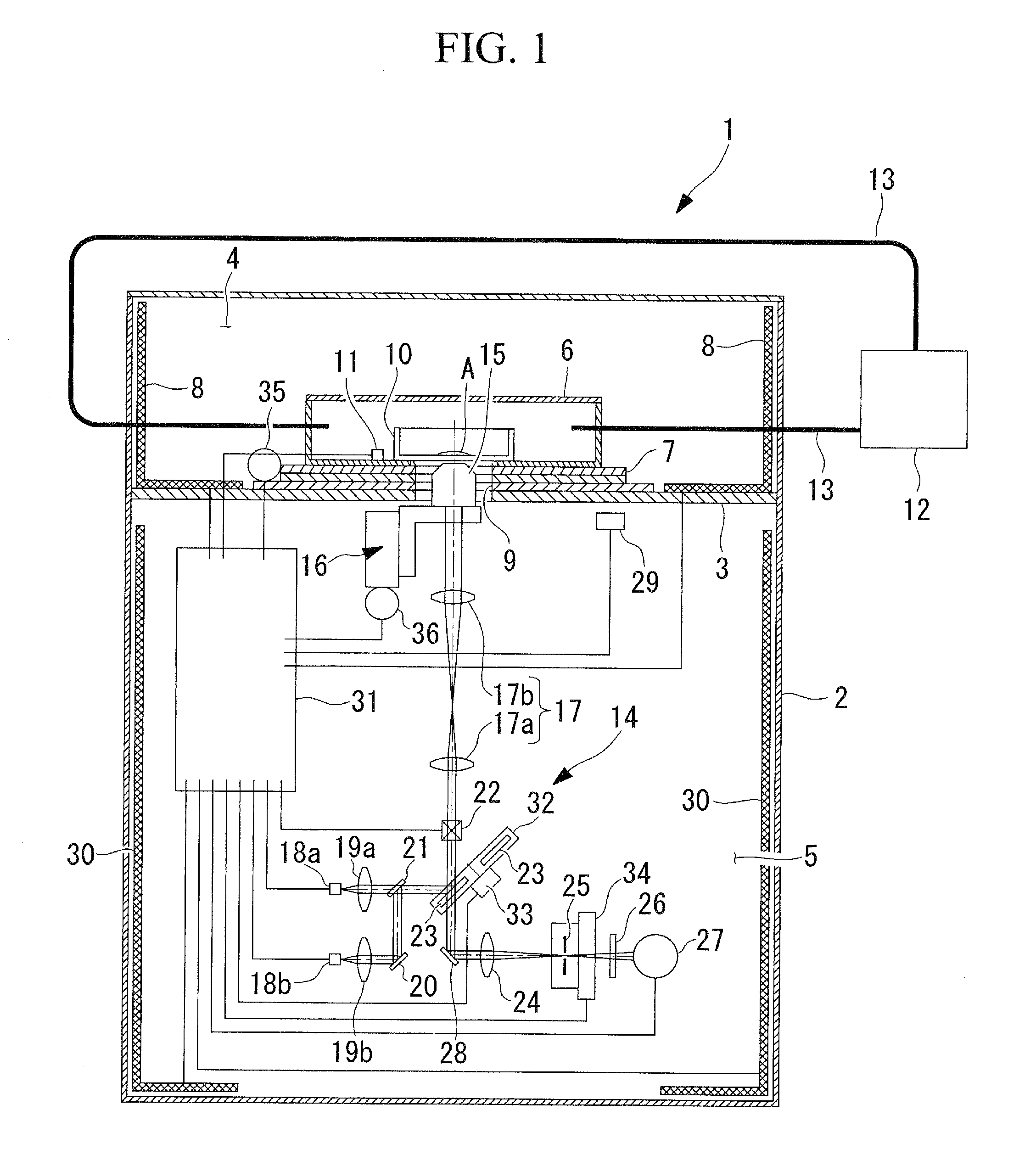
[0077]A scanning confocal microscope 1 according to an embodiment of the present invention will now be described with reference to FIG. 1.

[0078]In FIG. 1, the scanning confocal microscope 1 according to this embodiment includes an outer cover 2 having a rectangular box shape and formed of a heat insulator and a partition 3 disposed horizontally in the outer cover 2 to partition the inner space into an upper examination space 4 and a lower optical system space 5.

[0079]The upper examination space 4 accommodates an incubation container 6, a motor-driven stage 7 supporting the incubation container 6, and a heater (heating unit or temperature-maintaining unit for an examination space) 8.

[0080]The incubation container 6 is mounted on the motor-driven stage 7 and can be moved horizontally, for example, by the operation of the motor-driven stage 7.

[0081]A through-hole 9 extends vertically through the bottom of the incubation container 6, the motor-driven stage 7, and the partition 3 so that...


PUM


Abstract

A scanning confocal microscope can provide an image while preventing a decrease in brightness and blurring due to strain caused in optical and mechanical systems by thermal effects in a high-temperature, high-humidity incubation container. This scanning confocal microscope includes an incubation container that has a space in which a specimen is disposed and that can maintain an internal environment thereof at a predetermined temperature and high humidity and an optical system space adjacent to the incubation container and separated therefrom based on humidity. The optical system space accommodates a light-scanning unit and a scanner optical system, an objective lens, a confocal pinhole, and a focus adjustment mechanism. The optical system space further accommodates a temperature-maintaining unit for the optical system space to maintain the optical system space at a temperature substantially equal to the temperature in the incubation container.

Description

BACKGROUND OF THE INVENTION[0001]1. Field of the Invention[0002]The present invention relates to scanning confocal microscopes.[0003]This application is based on Japanese Patent Application No. 2007-098630, the content of which is incorporated herein by reference.[0004]2. Description of Related Art[0005]Among known microscopes is a scanning confocal microscope, which is capable of observation with three-dimensional resolution by detecting light through a confocal pinhole (for example, see Japanese Unexamined Patent Application, Publication No. 2004-86009).[0006]Also known is an examination system for long-term examination of changes in living cells over time (for example, see Japanese Unexamined Patent Application, Publication No. 2006-115760). To allow the cells to live for a long period of time, this system includes an incubator, mounted on a stage of an inverted microscope, for providing the cells with a high-temperature, high-humidity environment, and the incubator is maintained...

Claims


Application Information

Patent Timeline
IPC IPC(8): G02B21/26
CPCG02B21/0024G02B21/0088G02B21/26G02B21/30G02B21/33G02B21/34
Inventor SASAKI, HIROSHINAKATA, TATSUO
Owner OLYMPUS CORP
Why Eureka
Try Eureka