
Surgical machine and method for controlling and/or regulating a surgical machine

a surgical machine and control technology, applied in the field of surgical machines, can solve the problems of recurring problems with the maintenance and cleaning of the machine, the design of such machines and their operation are very complicated,

Active Publication Date: 2011-10-04
AESCULAP AG
View PDF62 Cites 807 Cited by
  • Summary
  • Abstract
  • Description
  • Claims
  • Application Information

AI Technical Summary

Benefits of technology

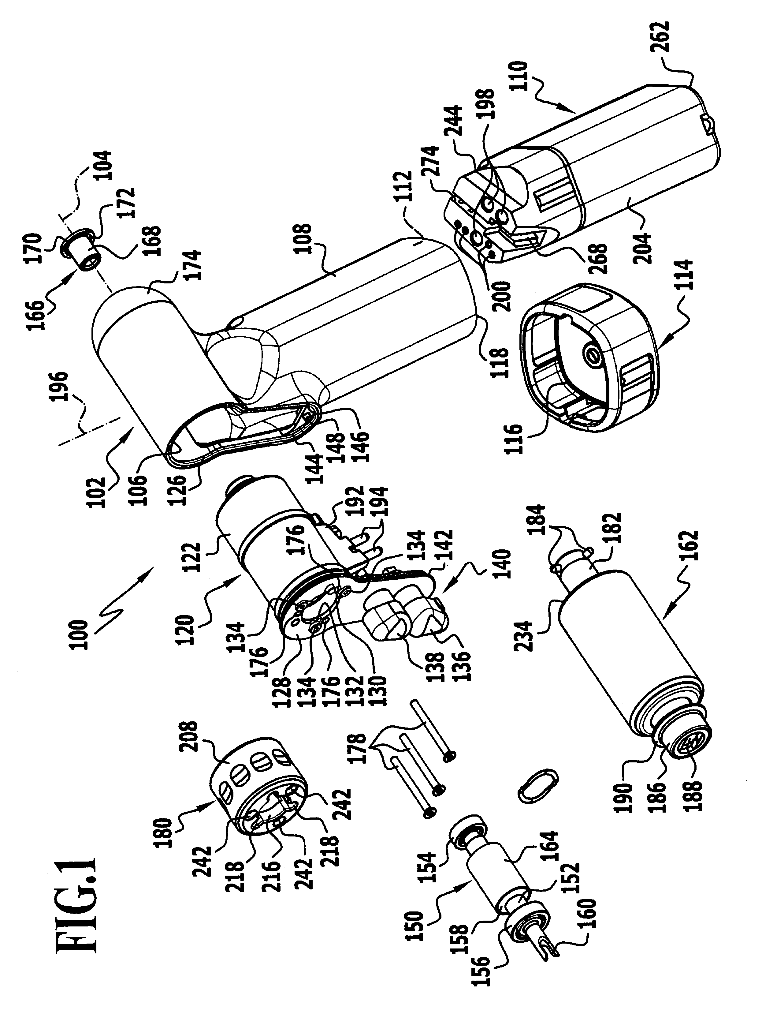
[0007]The surgical machine can thus be disassembled particularly easily, for example, by separating the drive and the housing. The drive can be connected to the housing directly, for example, by corresponding attachment mechanisms or indirectly, for example, by clamping between two elements that are directly connectable to the housing. The drive can thus be detached from the housing in a simple way, for example, for cleaning purposes or for exchange of the motor, in particular, on account of a defect, or for maintenance purposes.
[0161]It is advantageous for the machine to be operated in pilgrim step operation so long as a rotational speed which lies below a switchover rotational speed is prescribed with the first actuating member. It is also conceivable to operate the machine in pilgrim step operation when a requested rotational speed lies above a switchover rotational speed.

Problems solved by technology

In some cases, both the design of such machines and their operation are very complicated.
Also problems with the maintenance and cleaning of the machines keep recurring.

Method used


Image

  • Surgical machine and method for controlling and/or regulating a surgical machine
  • Surgical machine and method for controlling and/or regulating a surgical machine
  • Surgical machine and method for controlling and/or regulating a surgical machine

Examples


second embodiment

[0219]a surgical machine in the form of a jigsaw 300 is shown in FIGS. 5a to 8a. A large number of the components and component assemblies of the jigsaw 300 correspond to components or component assemblies of the accumulator machine 100, as is clearly apparent from a comparison of the Figures. In particular, the housings 102 and 302 are identical, and also the power and control unit 110, not shown in FIGS. 5a to 8a, which is designed in like manner to that in the accumulator machine 100 and can be held in the grip 308 of the housing 302 with a cover, not shown, which is identical to the cover 114.

[0220]The housing 302 comprises a motor mount 306 defining a longitudinal axis 304, and a grip 308 protruding substantially transversely from the motor mount 306 and defining a longitudinal axis 396. A drive unit 320 can be pushed parallel to the longitudinal axis 304 into an opening 326 defined on the front side of the housing 302 in the area of the motor mount 306 and the area of transiti...

third embodiment

[0240]a surgical machine according to the invention in the form of an oscillating saw, generally designated by reference numeral 500, is shown in FIGS. 9 to 15. The design of the saw 500 corresponds substantially to that of the jigsaw 300, so that identical parts or components are designated by reference numerals between 500 and 699, which are used in analogy with the reference numerals 300 to 499 used to describe the jigsaw 300.

[0241]The power and control unit 110 comprising the motor controller 246 serves as power supply. The power and control unit 110 can be pushed into a receiving space 509 of a grip 508 of a housing 502 and secured by closing the opening 512 with a cover corresponding to the cover 114. The grip 508 protrudes substantially transversely from a motor mount 506, which defines a longitudinal axis 504. The cover for closing the opening 512 has a seal, which presses against a lower rim of the grip 518 and thereby closes the receiving space 509 in a germ-proof manner.

[...


PUM


Abstract

In order to so improve a surgical machine comprising a housing and a surgical drive that maintenance of the machine is simplified, it is proposed that the drive and the housing be directly on indirectly connectable in a detachable manner.A method for controlling and / or regulating a surgical machine is also proposed.

Description

[0001]This application is a continuation of international application number PCT / EP2005 / 004059 filed on Apr. 16, 2005.[0002]The present disclosure relates to the subject matter disclosed in international application number PCT / EP2005 / 004059 of Apr. 16, 2005, which is incorporated herein by reference in its entirety and for all purposes.BACKGROUND OF THE INVENTION[0003]The present invention relates to a surgical machine with a housing and a surgical drive.[0004]Machines of the kind described at the outset are used in different variants and embodiments in surgery. Examples of such machines are drilling machines, milling machines and saws, in particular, jigsaws and oscillating saws. In some cases, both the design of such machines and their operation are very complicated. Also problems with the maintenance and cleaning of the machines keep recurring.[0005]The object of the present invention is, therefore, to so improve a machine and a method of the kind described at the outset that the...

Claims


Application Information

Patent Timeline
Patent Type & Authority Patents(United States)
IPC IPC(8): A61B17/00
CPCA61B17/1613A61B17/1626A61B17/1628A61B2019/4868Y10S388/907A61B2090/0813
Inventor HOEGERLE, ROLAND ALOIS
Owner AESCULAP AG
Learn More