Method and apparatus to improve vehicle situational awareness at intersections

a technology for intersections and vehicles, applied in the field of methods and apparatus to improve vehicle situational awareness at intersections, can solve the problems of institutional and not technical full-scale implementation, the annual tally of motor vehicle-related fatalities barely registers as a blip in most people's minds, and all vehicles need to be equipped, so as to improve the situational awareness of vehicles, the effect of easy to s

Inactive Publication Date: 2011-10-04
SMITH ALEXANDER E
View PDF45 Cites 208 Cited by
  • Summary
  • Abstract
  • Description
  • Claims
  • Application Information

AI Technical Summary

Benefits of technology

The present invention includes a number of embodiments for improving vehicle situational awareness at intersections. A first embodiment may comprise a lens fitted at the top of the windshield or outside the vehicle, for refracting the light to the driver, so the driver may more easily see signals, signage and other features of an intersection, as well as other traffic.

Problems solved by technology

“Yet, the annual tally of motor vehicle-related fatalities barely registers as a blip in most people's minds.”
While these systems have been designed, built and no doubt work effectively, the problem with full-scale implementation is institutional and not technical.
The big issue with cooperative devices is that all vehicles need to be equipped to provide benefits overall.
As in aviation, if one vehicle in a particular scenario is not equipped, the entire system is rendered useless and may be unsafe.
These frequencies have some disadvantages, however, and frequencies of approximately 24 Gigahertz are better for near-field monitoring.
While, as for the mobile phone industry, features are constantly added to in-car GPS units, these features are mainly limited to the somewhat obvious addition of user applications that run on the GPS unit's processor, with a lesser degree of integration to the GPS unit's main routing and guidance functions.
However, they quickly point out all of the impracticalities of such a scheme due to variations in different car headlamp intensities, not to mention differing ambient light conditions.
The system is used when a vehicle that is traveling in a series of consecutive vehicles stops due to traffic lights or a traffic jam, and the operator often fails to move the vehicle forward immediately after the traffic light changes or the traffic jam is cleared.
This failure to move the vehicle forward may cause further delays or traffic jams to occur.
According to the 2007 Urban Mobility Report, by D. Schrank and T. Lomax, of the Texas Transportation Institute, Texas A&M University System, incorporated herein by reference, traffic signal timing may be a significant source of delay.
The authors further conclude that non-peak travelers are subjected to approximately 30 hours of delay annually.
However, the effectiveness of the system is not known as all visible light may be decomposed into RGB primary colors and the data flow for the recognition process may be very substantial.
Furthermore, the effectiveness of this approach in various environments and lighting conditions is unknown.
The images are road surface markings at the lower end of a screen, making it difficult to predict specific positions of road surface markings.
Further, the angle of depression of the camera is large, and has a short period of time to acquire the object leading to low quality recognition and false marking recognition.
However, these devices merely serve as cameras and video displays, which supplant or augment traditional rear-view mirror displays.
They do not provide any automated detection features.
Since BUS is camera-based, it has the same limitations as the human eye does.
This means the system may not function in conditions of poor visibility, for instance in fog or flying snow.
Although there is generally a lot of talk about the introduction of new traffic management infrastructures and data linking between vehicles, it may take many years for any type of system that is cooperative and relies on high vehicle equipage scenarios.
Schofield would appear to suffer from a number of technical problems.
While it is possible to detect the frequency of light from a traffic signal, other lights (advertising, automotive, and the like) may also be at the same frequency, possibly generating false signals.
In addition in complex or sequential intersections, where multiple traffic lights are within the field of view of the device, it may be difficult to discriminate the correct signal for a given intersection and lane within an intersection.
However, his photodiode system would seem to have the same issues as Schofield, as it would not detect a traffic signal unless the diode was aimed properly.
In addition, it is not clear how the system would react to multiple signals in the same area (green arrows, adjacent or subsequent lights, complex intersections) so the incidence of false alarms could be common (with dangerous results, if a driver relies upon a false green indicator).
It also appears that Doan's device might trigger on other types of lighting (signage, advertisements, neon, car lights, etc.) as a photodiode is not very discriminating.
Areas with large numbers of colorful lighted signs (e.g., Times Square) might overwhelm such a simple detector.
Image sensing has its own problems, of course.
Again, multiple traffic lights in the field of view may confuse the system.
As automobile use expands worldwide, traffic congestion increases, driver distractions increase, and driver skills continue to deteriorate, the number of accidents at intersections will increase over time, resulting in death, personal injuries, and increased costs for motorists for insurance and repairs.

Method used


Image

  • Method and apparatus to improve vehicle situational awareness at intersections
  • Method and apparatus to improve vehicle situational awareness at intersections
  • Method and apparatus to improve vehicle situational awareness at intersections

Examples


first embodiment

The present invention includes a number of embodiments for improving vehicle situational awareness at intersections. A first embodiment may comprise a lens fitted at the top of the windshield or outside the vehicle, for refracting the light to the driver, so the driver may more easily see signals, signage and other features of an intersection, as well as other traffic.

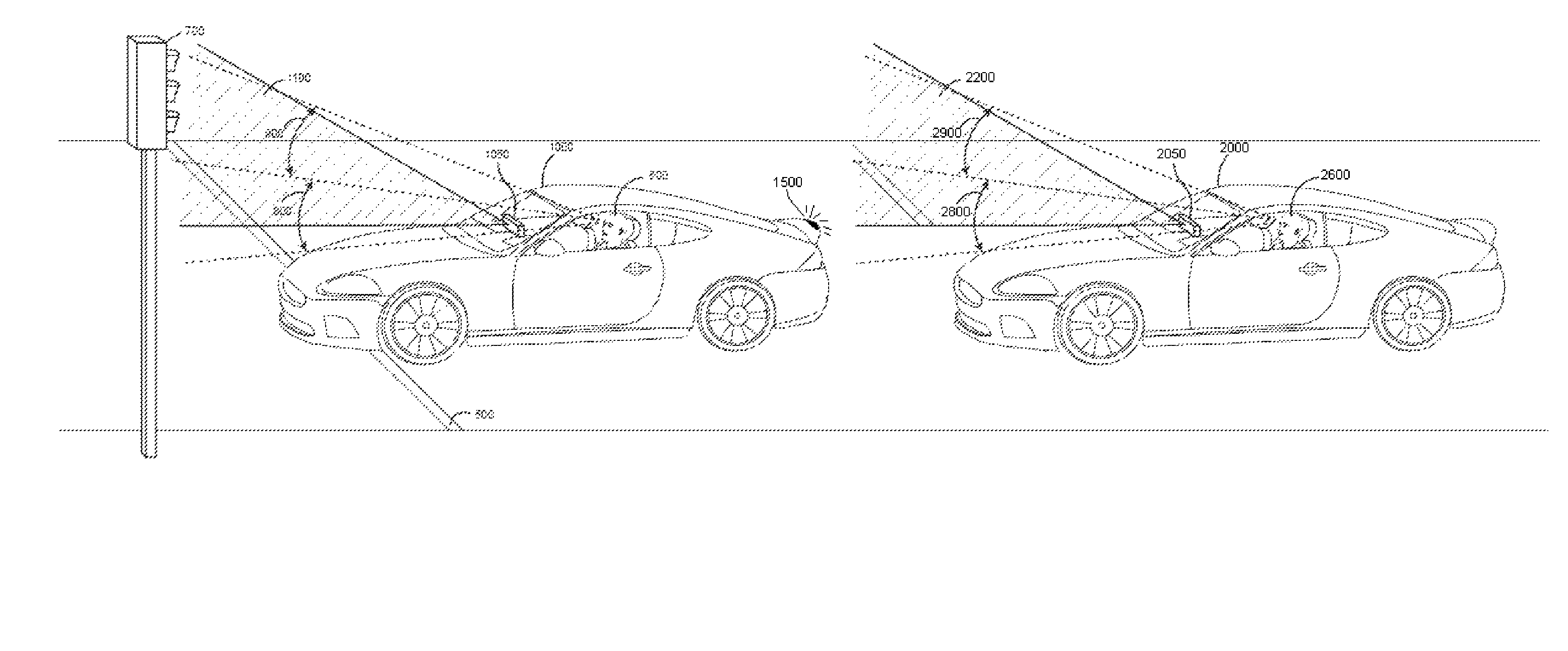
FIG. 8 is a diagram illustrating a typical driver position 100 in an automobile, with the location of the rear view mirror 200 and the general field of vision for observing traffic lights 300. Note that this field of vision 300 may be partially blocked by rear view minor 200. In addition, for taller drivers, this field of vision may be obstructed by the roof of the car, such that a taller driver cannot readily see a traffic signal if the car is too close to the signal, unless the driver cranes his neck.

In the context of the vehicle's position, FIG. 9 is a diagram illustrating an automobile at the stop line 500 at an in...

second embodiment

the invention is used as an aid to prompt the driver that a light has changed. When used as an aid for situational awareness the system may not have to be exact, but merely good enough to recognize a change in light status and prompt the driver to look at the lights before proceeding. As illustrated in FIG. 9, in many situations, a driver who is first in line at a traffic intersection may not be able to readily see the traffic light without craning their neck or looking under the windshield header. As a result, such a driver may not be readily aware when a light changes, causing a delay in movement of traffic. If a driver accelerates too late, only a few cars may make it through the intersection before the light changes. During heavy traffic, this may rapidly cause a backup at a traffic light, resulting in driver frustration, road rage, and the like. Such situations also encourage drivers to accelerate through the intersection even after the light has changed to yellow or even red, ...

third embodiment

In the present invention, the light change sensor may be combined with other vehicle status information as shown in the decision chart in FIG. 10. This embodiment uses additional data to confirm that the signals received are actually traffic signals intended for the vehicle, and are not traffic signals for adjacent lanes, successive intersections, or mere images of a traffic signal on a billboard.

As the car comes to a stop in step 10, the route guidance system (e.g., Global Positioning System (GPS) based guidance system or the like) may determine if the vehicle is at or in the vicinity of an intersection in step 20, using the route guidance database and GPS (or other tracking device) position data to determine the location of the vehicle. Vehicle speed and whether the vehicle has stopped can be determined from a vehicle tracking system or onboard vehicle speed sensors, or a combination of sensors. One set of sensors may be used to confirm the status of another. Thus, for example, th...


PUM


Abstract

The present invention includes a number of embodiments for improving vehicle situational awareness at intersections. A first embodiment may comprise a lens fitted at the top of the windshield or outside the vehicle, for refracting the light to the driver, so the driver may more easily see signals, signage and other features of an intersection, as well as other traffic. A second embodiment of the invention is used as an aid to prompt the driver that a light has changed. In a third embodiment, the light change sensor may be combined with other vehicle status information. As the car comes to a stop, the route guidance system may determine if the vehicle is at or in the vicinity of an intersection. Depending on the route guidance database, the system may also know whether or not there are traffic lights at the intersection. Using the vehicle's on board forward-looking radar sensor, the system may then determine if it is first in line at the intersection. In a fourth embodiment the system may be part of a portable after-market routing device. In a fifth embodiment the system, either portable or fixed, may be used to detect changes in the intensity of the brake lights of the vehicle ahead.

Description

FIELD OF THE INVENTIONThe present invention relates to a method and apparatus to improve the flow of traffic on the nation's roadways, specifically at or upon approach to intersections that have traffic lights. With the proliferation of lighted intersections to control traffic and the seemingly increasing time that drivers have to wait for traffic light changes, the present invention automatically prompts a driver when a light change is detected, thereby improving driver response and reducing the cumulative wait time at intersections, thus benefiting all road users.BACKGROUND OF THE INVENTIONAuto accidents cost each American more than $1,000 a year, 2½ times the cost of the traffic jams that frustrate the nation's drivers, according to a report issued by the American Automobile Association (AAA). According to the AAA report, accidents cost $164.2 billion each year, which based on the methodology used in the report, comes to an annual per person cost of $1,051. AAA said the study tha...

Claims


Application Information

Patent Timeline
Patent Type & Authority Patents(United States)
IPC IPC(8): B60Q1/00
CPCG08G1/0962G08G1/16G08G1/166
Inventor SMITH, ALEXANDER E.
Owner SMITH ALEXANDER E
Why Eureka
Try Eureka