
Optical touchpad system and waveguide for use therein

a touchpad and waveguide technology, applied in the field of optical touchpad systems, can solve the problems of limiting the use of conventional optical touchpad systems, affecting the use of optical touchpads, etc., to achieve enhanced frame rate, reduce optical noise in optical signals, and augment the ruggedness of optical touchpads

Inactive Publication Date: 2011-10-04
FLATFROG LAB
View PDF55 Cites 49 Cited by
  • Summary
  • Abstract
  • Description
  • Claims
  • Application Information

AI Technical Summary

Benefits of technology

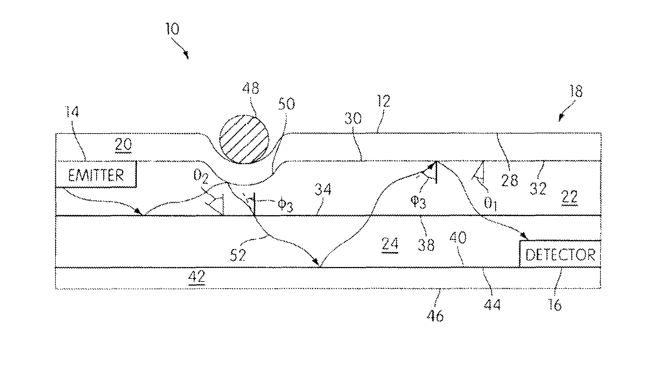
[0008]This configuration of optical touchpad provides various advantages over known touchpads. For example, the optical touchpad that may be able to function independent from a topology and / or opacity of an interface surface of the optical touchpad. This may enable the interface surface to be composed of any of a variety of materials (e.g., metal, wood, colored glass, colored polymers, clear glass, clear polymers, etc.). This may further enable the interface surface to include various topologies adapted for different applications in which the optical touchpad may be employed (e.g., appliances, doorbells, remote controls, personal electronics, keyboards, antiglare finishes, camera lenses, scroll buttons, tactile control input, Braille text, joysticks, applicable buttons, etc.). The operation of the optical touchpad may further enable an enhanced frame rate, reduced optical noise in the optical signal(s) guided to the one or more sensors, augment the ruggedness of the optical touchpad, and / or provide other advantages.

Problems solved by technology

However, conventional optical touchpad systems may include various drawbacks.
For example, conventional optical touchpad systems may be costly, imprecise, temperamental, fragile, energy inefficient, or may have other weaknesses and / or drawbacks.
These limitations on topology and / or opacity may restrict the use of these systems with respect to some of the applications for touchpad systems.
Various other drawbacks exist with known touchpads, including optical touchpads.

Method used


Image

  • Optical touchpad system and waveguide for use therein
  • Optical touchpad system and waveguide for use therein
  • Optical touchpad system and waveguide for use therein

Examples


Embodiment Construction

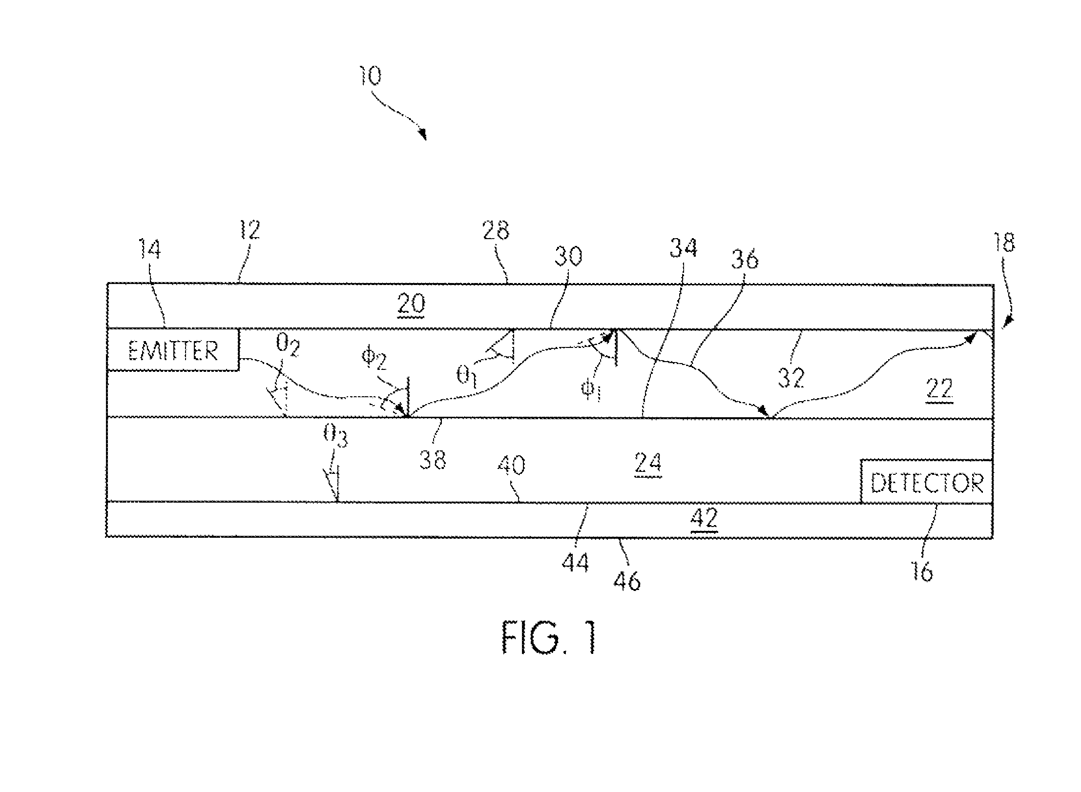
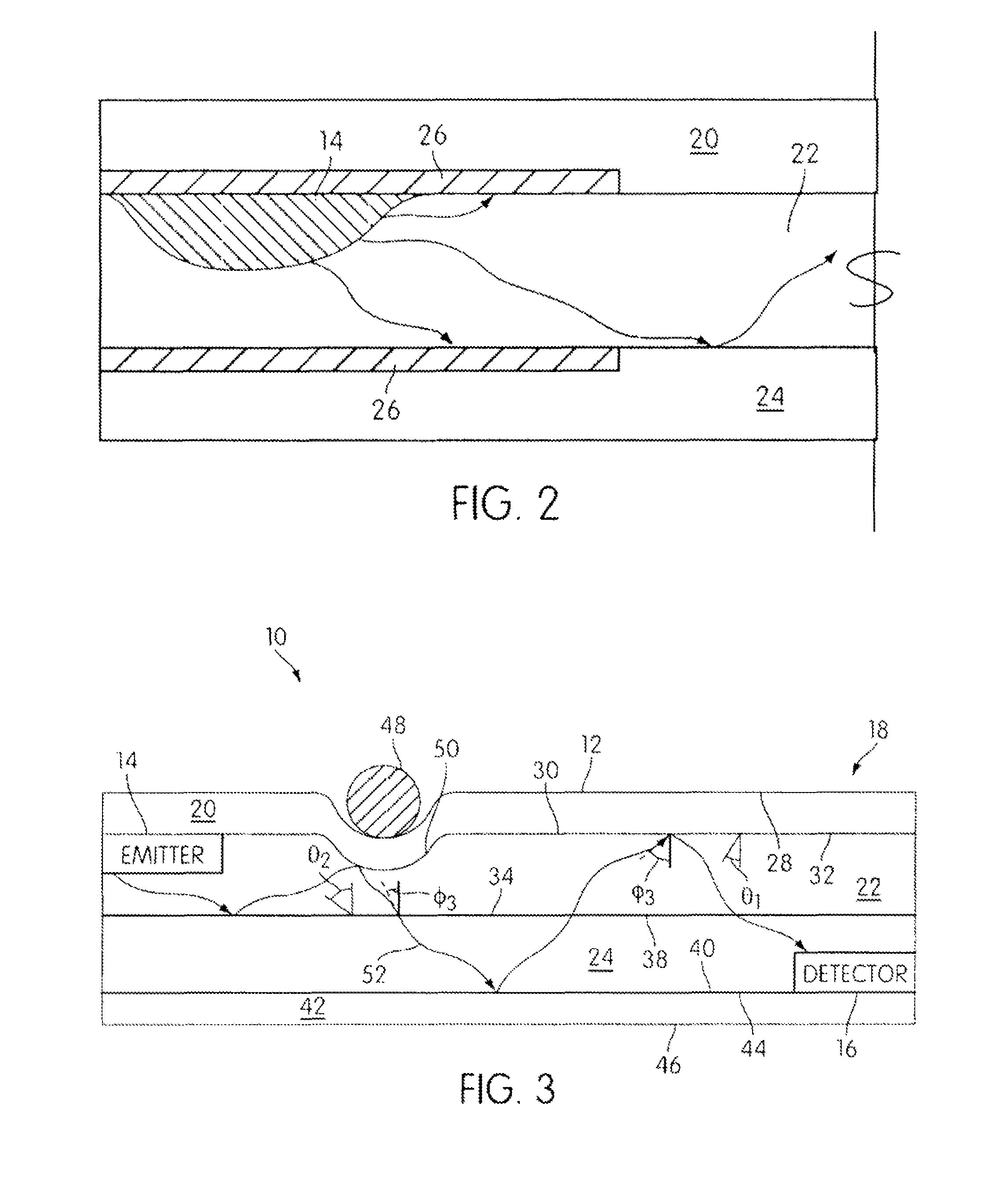
[0016]FIG. 1 illustrates an optical touchpad system 10 according to one or more embodiments of the invention. Optical touchpad system 10 may include an interface surface 12, one or more emitters 14, one or more detectors 16, and a waveguide 18. Interface surface 12 is configured such that a user can engage interface surface 12 with an object (e.g., a fingertip, a stylus, etc.). Optical touchpad system 10 detects a position of the engagement between interface surface 12 and the object.

[0017]Emitters 14 emit electromagnetic radiation, and may be optically coupled with waveguide 18 so that electromagnetic radiation emitted by emitters 14 may be directed into waveguide 18. Emitters 14 may include one or more Organic Light Emitting Devices (“OLEDs”), lasers (e.g., diode lasers or other laser sources), Light Emitting Devices (“LEDs”), Hot Cathode Fluorescent Lamps (“HCFLs”), Cold Cathode Fluorescent Lamps (“CCFLs”) incandescent lamps, halogen bulbs, received ambient light, and / or other el...


PUM


Abstract

An optical touchpad system is disclosed that may be easily integrated into a variety of applications. One feature of the optical touchpad system that may contribute to this versatility may be the ability of the optical touchpad system to function in the same manner independent from a topology and / or opacity of an interface surface of the optical touchpad system. This may enable the interface surface to be composed of any of a variety of materials. This may further enable the interface surface to include various topologies adapted for the application in which the optical touchpad system may be employed.

Description

FIELD OF THE INVENTION[0001]The invention relates to a optical touchpad system, with a multilayer waveguide that includes at least one total internal reflection mirror, for determining information relating to an engagement between an object and an interface surface of the optical touchpad system.BACKGROUND OF THE INVENTION[0002]Generally, touchpad systems are implemented for a variety of applications. Some of these applications include, computer interfaces, keypads, keyboards, and other applications. Various types of touch pads are known. Optical touch pads have certain advantages over some other types of touch pads at least for some applications. Various types of optical touchpad systems may be used in some or all of these applications. However, conventional optical touchpad systems may include various drawbacks. For example, conventional optical touchpad systems may be costly, imprecise, temperamental, fragile, energy inefficient, or may have other weaknesses and / or drawbacks. Fur...

Claims


Application Information

Patent Timeline
Patent Type & Authority Patents(United States)
IPC IPC(8): G06F3/042
CPCG06F3/0421G06F2203/04109
Inventor OSTERGAARD, JENS WAGENBLAST STUBBE
Owner FLATFROG LAB
Learn More