Swirler with gas injectors

a gas injector and swirler technology, applied in the field of swirlers, can solve problems such as unsteady fluid dynamic processes, thermo-acoustic instabilities, and movement of flames, and achieve the effect of avoiding high thermal loading and avoiding problems related to burner mechanical integrity

Inactive Publication Date: 2011-10-11
SIEMENS AG
View PDF14 Cites 17 Cited by
  • Summary
  • Abstract
  • Description
  • Claims
  • Application Information

AI Technical Summary

Benefits of technology

[0017]The aspects of the invention are exemplified in combination with a Lean-Rich Partially Premixed Low Emissions Burner for a gas turbine combustor that provides stable ignition and combustion process at all engine load conditions. This burner operates according to the principle of “supplying” heat and high concentration of free radicals from the a pilot combustor exhaust to a main flame burning in a lean premixed air / fuel swirl, whereby a rapid and stable combustion of the main lean premixed flame is supported. The pilot combustor supplies heat and supplements a high concentration of free radicals directly to a forward stagnation point and a shear layer of the main swirl induced recirculation zone, where the main lean premixed flow is mixed with hot gases products of combustion provided by the pilot combustor. This allows a leaner mix and lower temperatures of the main premixed air / fuel swirl combustion that otherwise would not be self-sustaining in swirl stabilized recirculating flows during the operating conditions of the burner.
[0019]A swirl of air / fuel above Swirl number (SN) 0.7 (that is above critical SN=0.6), generated-imparted into the flow, by a radial swirler;active elements—providing high non-equilibrium of free radicals being released close to the forward stagnation point,particular type of the burner geometry with a multi quarl device, andinternal staging of fuel and air within the burner to stabilize combustion process at all gas turbine operating conditions.In short, the disclosed burner provides stable ignition and combustion process at all engine load conditions. Some important features related to the inventive burner are:the geometric location of the burner elements;the amount of fuel and air staged within the burner;the minimum amount of active elements—radicals generated and required at different engine / burner operating conditions;fuel profile;mixing of fuel and air at different engine operating conditions;imparted level of swirl;multi (minimum double quarl) quarl arrangement.
[0029]To achieve ultra-low emission, perfect premixing (flat fuel / air mixture profile) of the gaseous fuel and air is desirable to avoid concentration gradients at the flame front causing regions of high temperature. Furthermore, the premixing has to be finalized in a short distance. This is arrived at by means of the embodiments of the invention.
[0031]provides a flame front (main recirculation zone) anchoring the flame in a defined position in space, without a need to anchore the flame to a solid surface / bluff body, and in that way a high thermal loading and issues related to the burner mechanical integrity are avoided,geometry (quarl half angle α and length L) is important to control size and shape of the recirculation zone in conjunction with the swirl number. The length of the recirculation zone is roughly proportional to 2 to 2.5 of the quarl length,optimal length L is of the order of L / D=1 (D is the quarl throat diameter). The minimum length of the quarl should not be smaller then L / D=0.5 and not longer then L / D=2,optimal quarl half angle α should not be smaller then 20 and larger then 25 degrees, allows for a lower swirl before decrease in stability, when compared to a less confined flame front, andhas the important task to control the size and shape of the recirculation zone as the expansion of the hot gases as a result of combustion reduces transport time of free radicals in the recirculation zone.

Problems solved by technology

The major problems associated with the combustion process in gas turbine engines, in addition to thermal efficiency and proper mixing of the fuel and the air, are associated to flame stabilization, the elimination of pulsations and noise, and the control of polluting emissions, especially nitrogen oxides (NOx), CO, UHC, smoke and particulated emission.
A less stable, easy to move flame front of a pre-mixed flame results in a periodic heat release rate, that, in turn, results in movement of the flame, unsteady fluid dynamic processes, and thermo-acoustic instabilities develop.
When the heat required for reactions to occur is the stability-limiting factor, very small temporal fluctuations in fuel / air equivalence ratios (which could either result either from fluctuation of fuel or air flow through the Burner / Injector) can cause flame to partially extinguish and re-light.
When the flame can, more easily, occur in multiple positions, it becomes more unstable.

Method used


Image

  • Swirler with gas injectors
  • Swirler with gas injectors
  • Swirler with gas injectors

Examples


Embodiment Construction

[0040]In the following a number of embodiments of the invention will be described in more detail with references to the enclosed drawings.

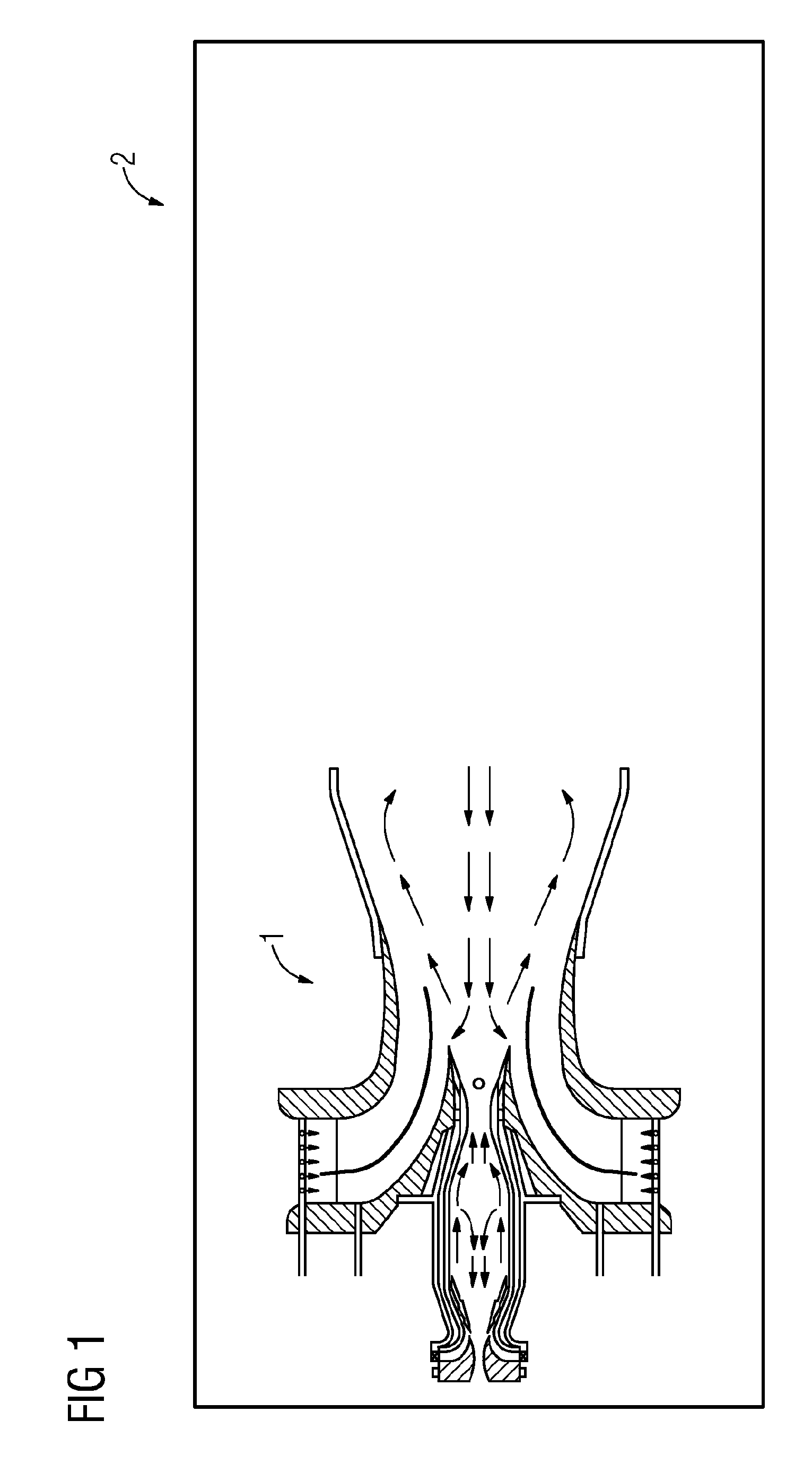
[0041]In FIG. 1 the burner is depicted with the burner 1 having a housing 2 enclosing the burner components.

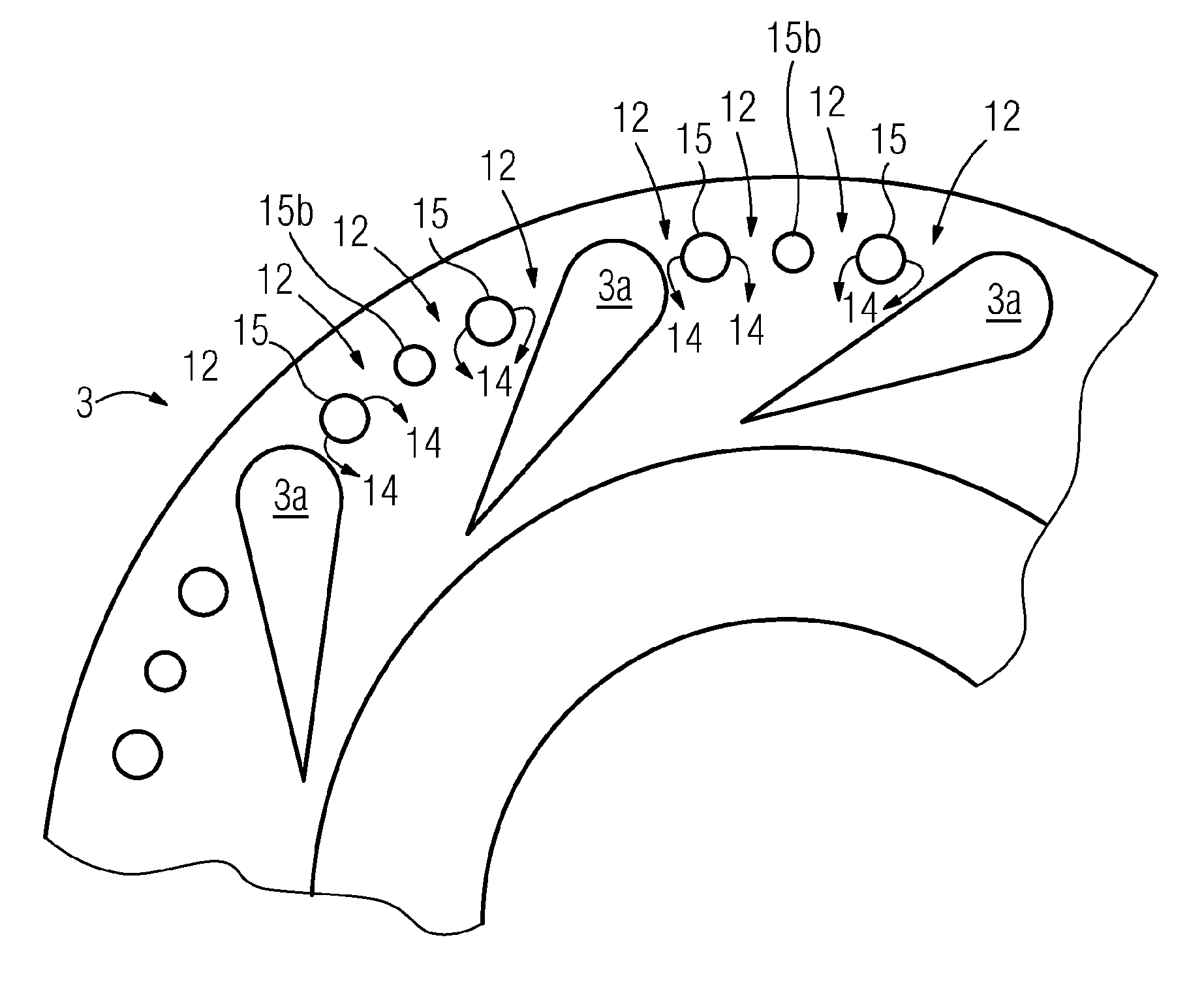
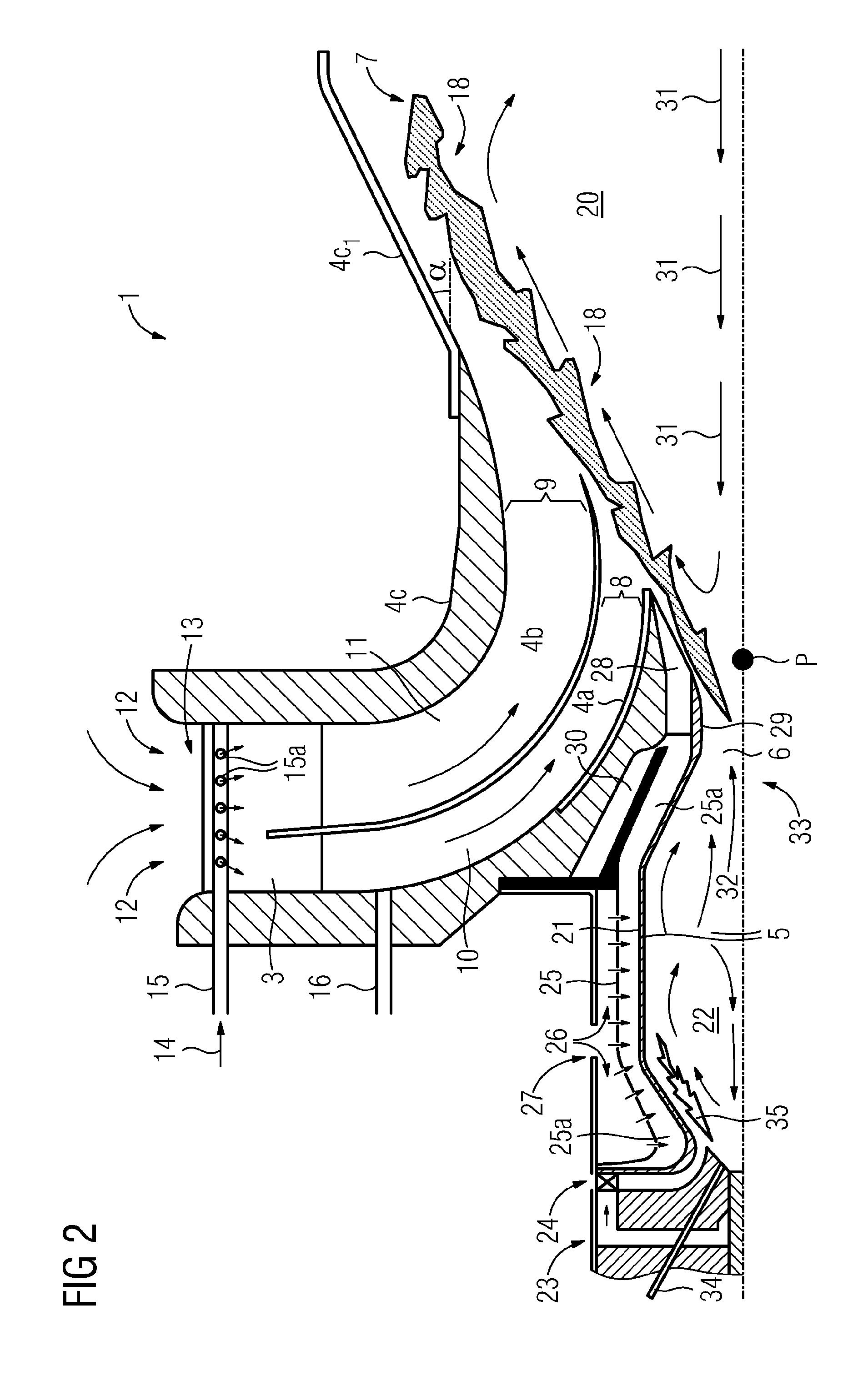
[0042]FIG. 2 shows for the sake of clarity a cross sectional view of the burner above a rotational symmetry axis. The main parts of the burner are the radial swirler 3, the multi quarl 4a, 4b, 4c and the pilot combustor 5.

[0043]As stated, the burner 1 operates according to the principle of “supplying” heat and high concentration of free radicals from the a pilot combustor 5 exhaust 6 to a main flame 7 burning in a lean premixed air / fuel swirl emerging from a first exit 8 of a first lean premixing channel 10 and from a second exit 9 of a second lean premixing channel 11, whereby a rapid and stable combustion of the main lean premixed flame 7 is supported. Said first lean premixing channel 10 is formed by and between the walls 4a and 4b of the...


PUM


Abstract

A swirler for premixing a flow of fuel and a flow of air provided to a burner for a gas turbine engine is provided. The burner is provided with a swirler for mixing the air and the fuel and wherein the swirler is provided with swirler wings, wherein a channel formed between two adjacent swirler wings defines a passage. The swirler includes one fuel tube for gaseous fuel positioned in parallel on each side of a mixing rod in the passage, wherein the fuel tubes are provided with a plurality of diffuser holes distributed along the tube acting as gas injectors for efficiently distributing fuel in a flow of air passing through the swirler passage.

Description

CROSS REFERENCE TO RELATED APPLICATIONS[0001]This application is the US National Stage of International Application No. PCT / EP2009 / 053563, filed Mar. 26, 2009 and claims the benefit thereof. The International Application claims the benefits of European Patent Office application No. 08006658.2 EP filed Apr. 1, 2008. All of the applications are incorporated by reference herein in their entirety.TECHNICAL FIELD[0002]The present invention refers to a swirler for use in a burner for a gas turbine engine, and more particularly a swirler having gas injectors for providing a mixture of gas and fuel to a combustion room of a burner of said type.TECHNICAL BACKGROUND[0003]Gas turbine engines are employed in a variety of applications including electric power generation, military and commercial aviation, pipeline transmission and marine transportation. In a gas turbine engine which operates in LPP mode, fuel and air are provided to a burner chamber where they are mixed and ignited by a flame, th...

Claims


Application Information

Patent Timeline
Patent Type & Authority Patents(United States)
IPC IPC(8): F02C1/00
CPCF23C7/004F23D14/02F23D14/70F23R3/14F23R3/286F23C2900/07001F23D2900/14021
Inventor MILOSAVLJEVIC, VLADIMIRPERSSON, ALLANPERSSON, MAGNUS
Owner SIEMENS AG
Why Eureka
Try Eureka