Shock absorber

a technology of shock absorber and shock absorber, which is applied in the direction of shock absorber, vibration damper, damper-spring combination, etc., can solve the problems of impaired passenger comfort in the vehicle, inability to suppress vibration, etc., and achieve the effect of improving the passenger comfort of the vehicle, reducing vibration, and increasing the shock absorber's generating for

Active Publication Date: 2011-10-25
KYB CORP
View PDF15 Cites 16 Cited by
  • Summary
  • Abstract
  • Description
  • Claims
  • Application Information

AI Technical Summary

Benefits of technology

[0007]This invention has been designed in consideration of this problem, and it is an object thereof to provide a shock absorber that can improve passenger comfort in a vehicle even when the expansion / contraction speed of the shock absorber is high.
[0009]According to this invention, when the expansion / contraction speed of the shock absorber is high, the valve body displaces in accordance with the pressure in one of the pressure chambers to close the second passage. At this time, the first passage and third passage communicate via the bypass passage. The flow passage area of the bypass passage is smaller than the flow passage area when the first passage and second passage are both open, and therefore, when the valve body closes the second passage, the damping force generated by the shock absorber increases. Hence, even when the expansion / contraction speed of the shock absorber is high, the damping force does not become insufficient, and vibration in the vehicle can be suppressed sufficiently, enabling an improvement in the passenger comfort of the vehicle.

Problems solved by technology

As shown in FIG. 9, when the piston speed increases, the damping force tends to become insufficient, making it impossible to suppress vibration in a vehicle sufficiently, and as a result, passenger comfort in the vehicle may be impaired.

Method used


Image

  • Shock absorber
  • Shock absorber
  • Shock absorber

Examples


first embodiment

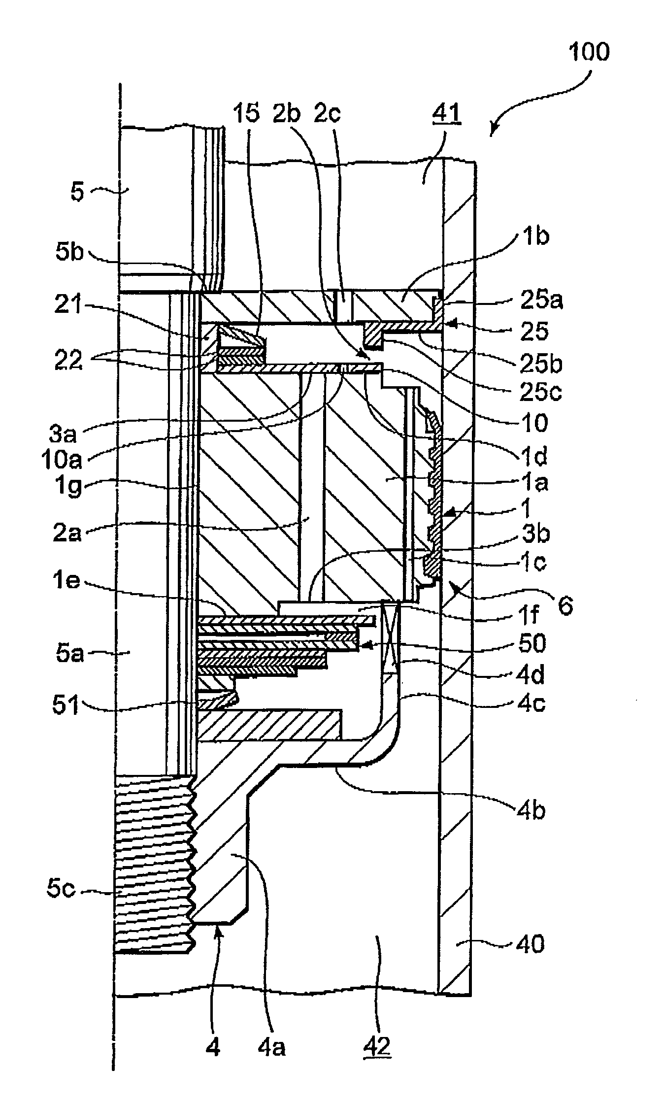
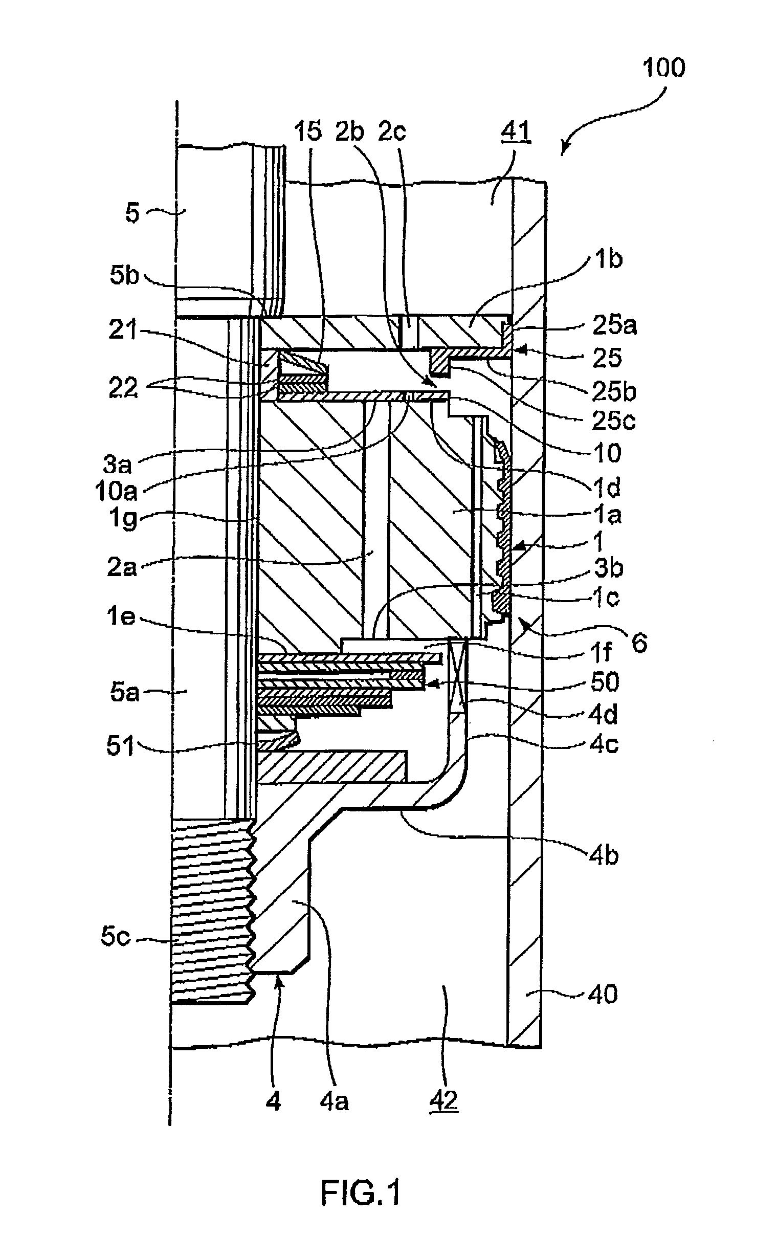
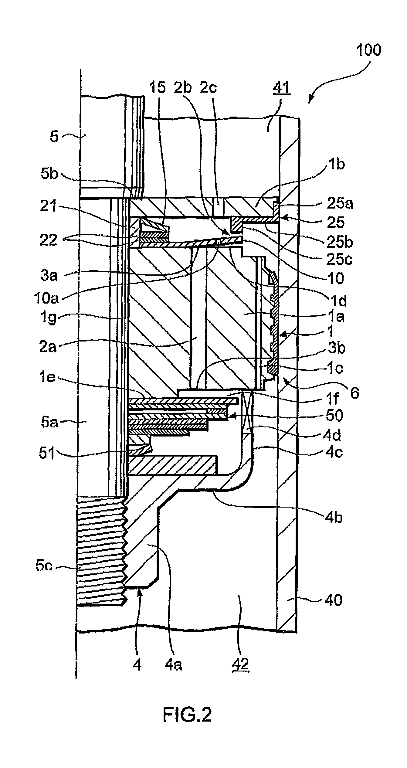
[0020]First, referring to FIGS. 1 to 3, a shock absorber 100 according to a first embodiment of this invention will be described.

[0021]The shock absorber 100 is interposed between a vehicle body and an axle of a vehicle in order to suppress vibration in the vehicle body, and as shown in FIG. 1, comprises a cylinder 40 in which a working fluid such as oil is sealed, a piston 1 serving as a valve disk that delineates two pressure chambers 41, 42 within the interior of the cylinder 40 and moves slidingly through the interior of the cylinder 40, and a rod 5, one end of which is connected to the piston 1 and another end of which extends to the exterior of the cylinder 40. A first passage 2a, a second passage 2b, and a third passage 2c are formed in series in the piston 1 to connect the pressure chambers 41 and 42 and allow the working fluid to pass therethrough. These passages 2a, 2b, 2c will be described later.

[0022]The shock absorber 100 further comprises a leaf valve 10 serving as a v...

second embodiment

[0072]Next, referring to FIGS. 6 to 8, a shock absorber 200 according to a second embodiment of this invention will be described. It should be noted that identical members to those of the shock absorber 100 according to the first embodiment described above have been allocated identical reference symbols, and description thereof has been omitted.

[0073]The difference between the shock absorber 200 and the shock absorber 100 of the first embodiment is that in place of the through hole 10a in the leaf valve 10, a groove 30 is provided in the projecting portion 25c of the dam portion 25. The following description will focus on this difference.

[0074]As shown in FIG. 7, the groove 30 is formed by cutting away a part of the annular projecting portion 25c.

[0075]When the shock absorber 200 performs a contraction operation such that the piston speed reaches the high speed region at or above the predetermined speed, the leaf valve 10 comes into contact with the projecting portion 25c. At this ...


PUM


Abstract

A shock absorber (100) for suppressing vibration in a vehicle includes a valve disk (1) that delimits the interior of a cylinder (40) in which a working fluid is sealed; a first passage (2a), a second passage (2b) and a third passage (2c), which are disposed in series so as to connect pressure chambers (41, 42) delimited by the valve disk (1); a valve body (10) that selectively opens the first passage (2a) and the second passage (2b); a biasing member (15) that biases the valve body (10) in a direction for closing the first passage (2a) against the pressure in one of the pressure chambers (42); and a bypass passage (10a) that connects the first passage (2a) to the third passage (2c) when the valve body (10), having displaced in accordance with the pressure in the one pressure chamber (42) so as to open the first passage (2a), displaces further so as to close the second passage (2b). The bypass passage (10a) is set to have a smaller flow passage area than a flow passage area when the first passage (2a) and the second passage (2b) are both open.

Description

TECHNICAL FIELD[0001]This invention relates to an improvement of a shock absorber.BACKGROUND ART[0002]A conventional shock absorber comprises a piston that is inserted into a cylinder so as to be free to slide and delineates two oil chambers within the interior of the cylinder, a port that penetrates the piston and is capable of connecting the two oil chambers, a leaf valve laminated onto an outlet opening portion of the port, and a spring that biases the leaf valve in a direction for closing the port outlet opening portion (see JP2004-190716, for example).[0003]In this type of shock absorber, the leaf valve is bent by a differential pressure between the two oil chambers, and the flow area of a passage through which a working fluid passes is determined by the bending amount of the leaf valve. A damping force generated by the shock absorber is determined according to the flow passage area.DISCLOSURE OF THE INVENTION[0004]When an expansion / contraction speed of the shock absorber is lo...

Claims


Application Information

Patent Timeline
Patent Type & Authority Patents(United States)
IPC IPC(8): F16F9/348F16F13/00F16F9/34
CPCF16F9/3485F16F9/34F16F9/348
Inventor OTA, AKIHISAKON, KENKICHI
Owner KYB CORP
Why Eureka
Try Eureka