Massaging device having completely massaging effect

a technology of massaging device and massaging belt, which is applied in the field of massaging belt, can solve the problems of restricting the massaging effect of the massaging device, and achieve the effects of enhancing the massaging effect of the massaging device, and comfortable sensation for users

Inactive Publication Date: 2011-10-25
WU DONG HER
View PDF5 Cites 17 Cited by
  • Summary
  • Abstract
  • Description
  • Claims
  • Application Information

AI Technical Summary

Benefits of technology

[0007]Another objective of the present invention is to provide a massaging device, wherein the massaging member is movable to massage the user's back reciprocally, and the two massaging belts are movable to massage the user's body reciprocally, so that the massaging device can be used to massage the user's body exactly and completely, thereby enhancing the massaging effect of the massaging device, and thereby providing comfortable sensation to the user.
[0008]A further objective of the present invention is to provide a massaging device, wherein the user's body is encircled by the two massaging belts, the two connecting straps and the massaging member, so that the user's body is pulled, rubbed, twisted and kneaded by movement and deflection of the two massaging belts, the two connecting straps and the massaging member, thereby greatly enhancing the massaging effect of the massaging device.
[0009]A further objective of the present invention is to provide a massaging device, wherein the massaging member can be used to massage the user's back, and the two massaging belts can be used to massage the user's waist and abdomen, thereby enhancing the versatility of the massaging device.

Problems solved by technology

However, the massaging mechanism 60 is used to massage a small part of the user's body only, thereby limiting the massaging effect of the massaging device.

Method used


Image

  • Massaging device having completely massaging effect
  • Massaging device having completely massaging effect
  • Massaging device having completely massaging effect

Examples


Embodiment Construction

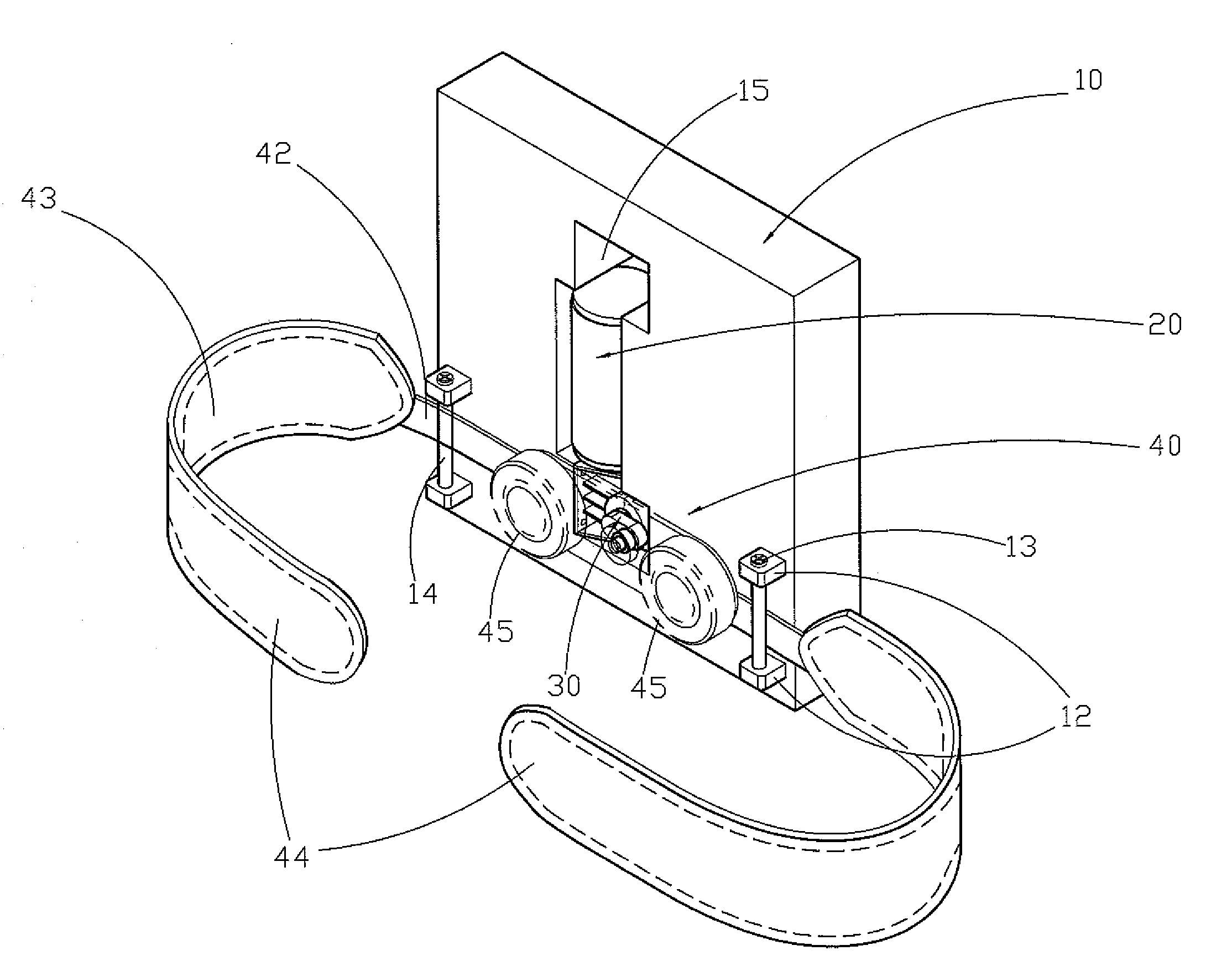
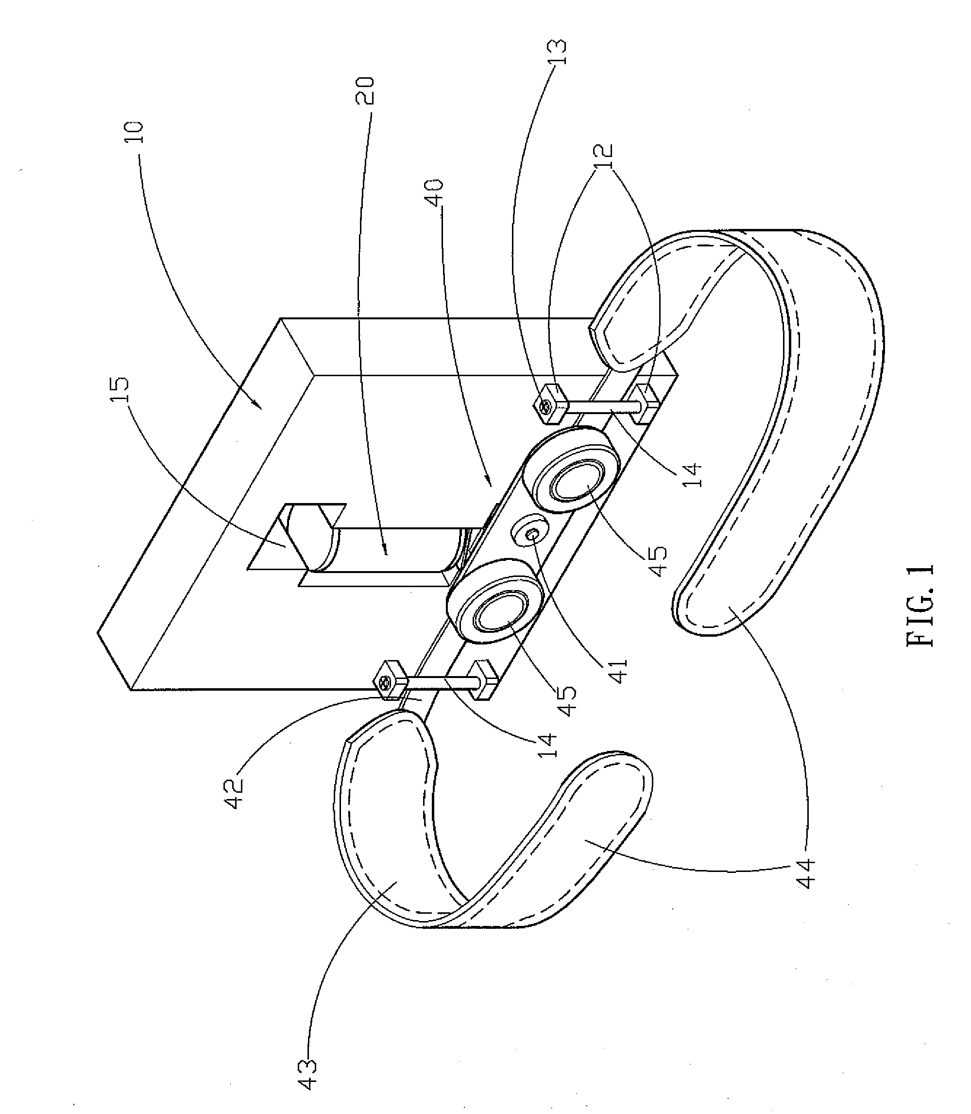
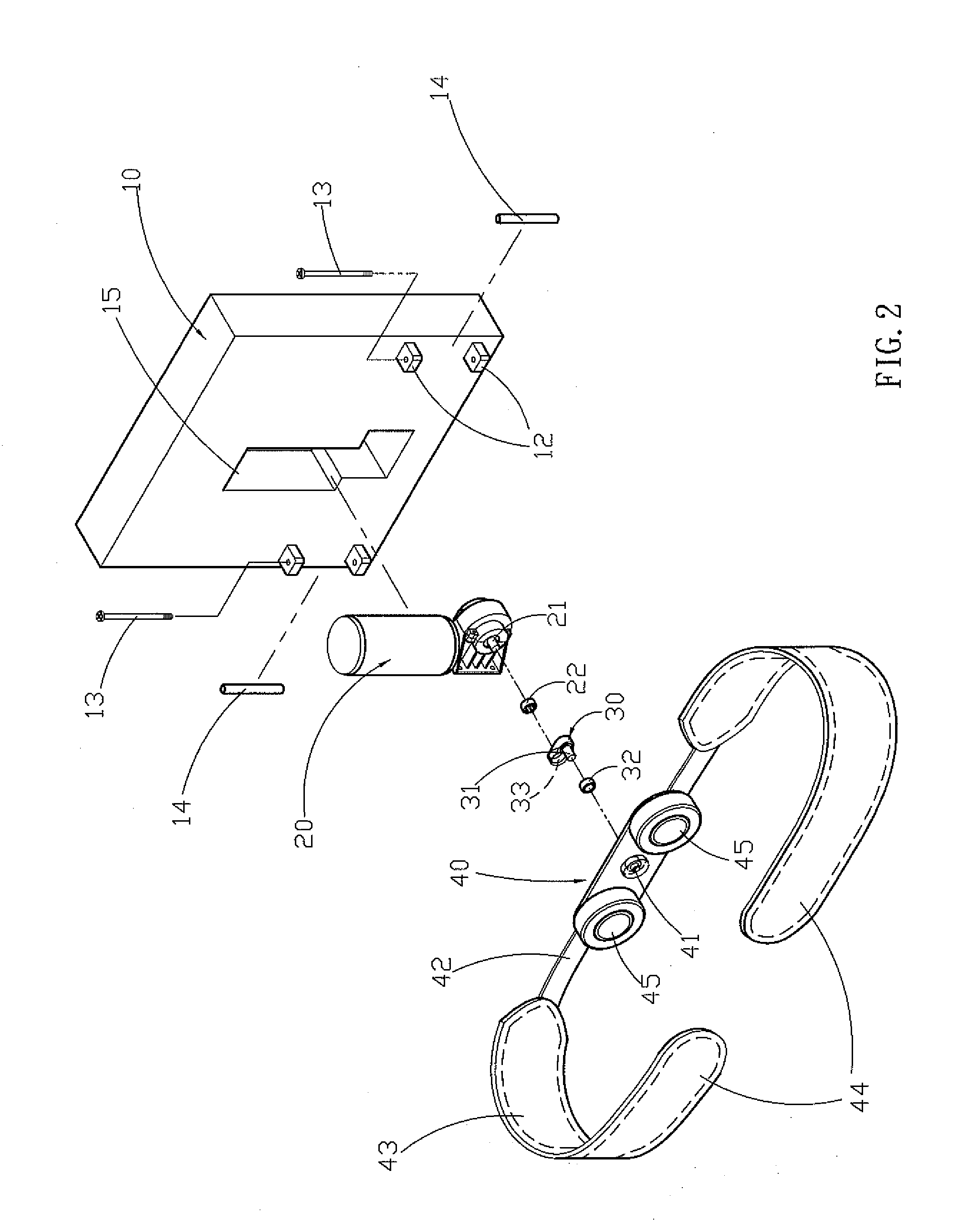
[0021]Referring to the drawings and initially to FIGS. 1-6, a massaging device in accordance with the preferred embodiment of the present invention comprises a support member 10, a massaging member 40 movably mounted on the support member 10, two opposite connecting straps 42 connected with the massaging member 40 respectively, two massaging belts 43 combined with each other and each connected with a respective one of the two connecting straps 42, a drive member 20 mounted on the support member 10 and provided with a rotation shaft 21, an eccentric member 30 mounted on and rotatable with the rotation shaft 21 of the drive member 20 and provided with an eccentric shaft 31 connected with the massaging member 40 to drive the massaging member 40 to move relative to the support member 10 by rotation of the eccentric member 30, and two support rods 14 each mounted on the support member 10 and each abutting a respective one of the two connecting straps 42.

[0022]The support member 10 is mad...


PUM


Abstract

A massaging device includes a support member, a massaging member movably mounted on the support member, two opposite connecting straps connected with the massaging member respectively, two massaging belts each connected with a respective one of the connecting straps, a drive member mounted on the support member and provided with a rotation shaft, and an eccentric member rotatable with the rotation shaft and provided with an eccentric shaft to drive the massaging member to move relative to the support member. Thus, the massaging member is movable to massage the user's back reciprocally, and the two massaging belts are movable to massage the user's body reciprocally, so that the massaging device can be used to massage the user's body exactly and completely.

Description

BACKGROUND OF THE INVENTION[0001]1. Field of the Invention[0002]The present invention relates to a massaging device and, more particularly, to a massaging device to provide a massaging effect to a user.[0003]2. Description of the Related Art[0004]A conventional massaging device in accordance with the prior art shown in FIGS. 9 and 10 comprises a hollow cushion 50, a support frame 51 mounted in the cushion 50, and a massaging mechanism 60 mounted on the cushion 50 and supported by the support frame 51. The massaging mechanism 60 includes a motor 62 mounted on the support frame 51 and provided with a rotation shaft 63, and two eccentric units 64 mounted on two opposite ends of the rotation shaft 63 of the motor 62 respectively. Each of the eccentric units 64 includes an eccentric member 641 having a first end mounted on the respective end of the rotation shaft 63 of the motor 62, a rotation member 642 mounted on a second end of the eccentric member 641 by a bearing 643, and a fastenin...

Claims


Application Information

Patent Timeline
Patent Type & Authority Patents(United States)
IPC IPC(8): A61H11/00
CPCA61H11/02A61H15/0078A61H2015/0028A61H2201/1215A61H2201/163
Inventor WU, DONG-HER
Owner WU DONG HER
Why Eureka
Try Eureka