Turbine airfoil with near-wall serpentine cooling

Active Publication Date: 2011-11-01
FLORIDA TURBINE TECH
View PDF11 Cites 28 Cited by
  • Summary
  • Abstract
  • Description
  • Claims
  • Application Information

AI Technical Summary

Benefits of technology

[0012]It is an object of the present invention to provide for a turbine airfoil with a leading edge cooling circuit that will greatly

Problems solved by technology

However, the single pass radial flow cooling channel with the drilled film cooling holes design is no

Method used


Image

  • Turbine airfoil with near-wall serpentine cooling
  • Turbine airfoil with near-wall serpentine cooling
  • Turbine airfoil with near-wall serpentine cooling

Examples


Embodiment Construction

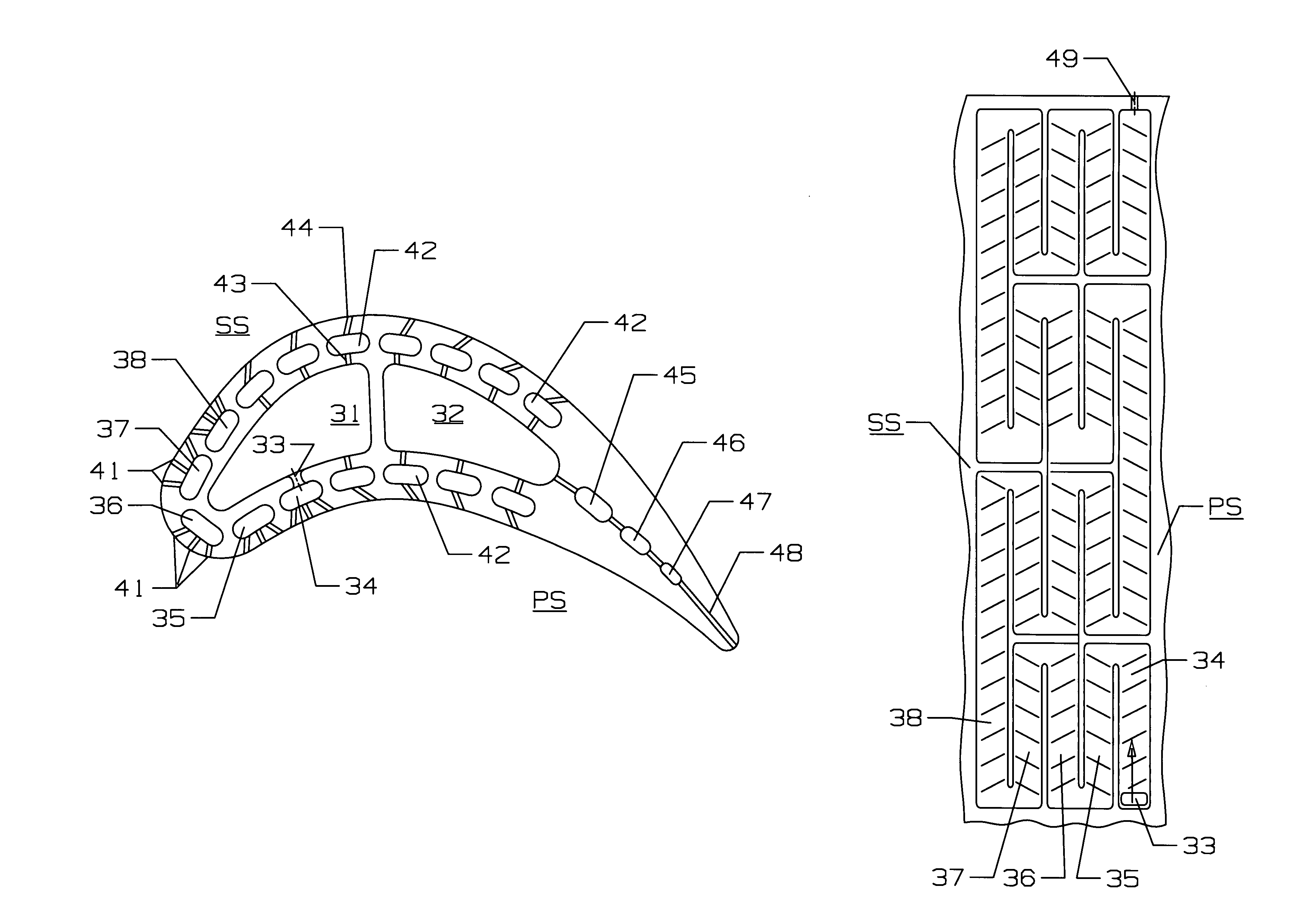
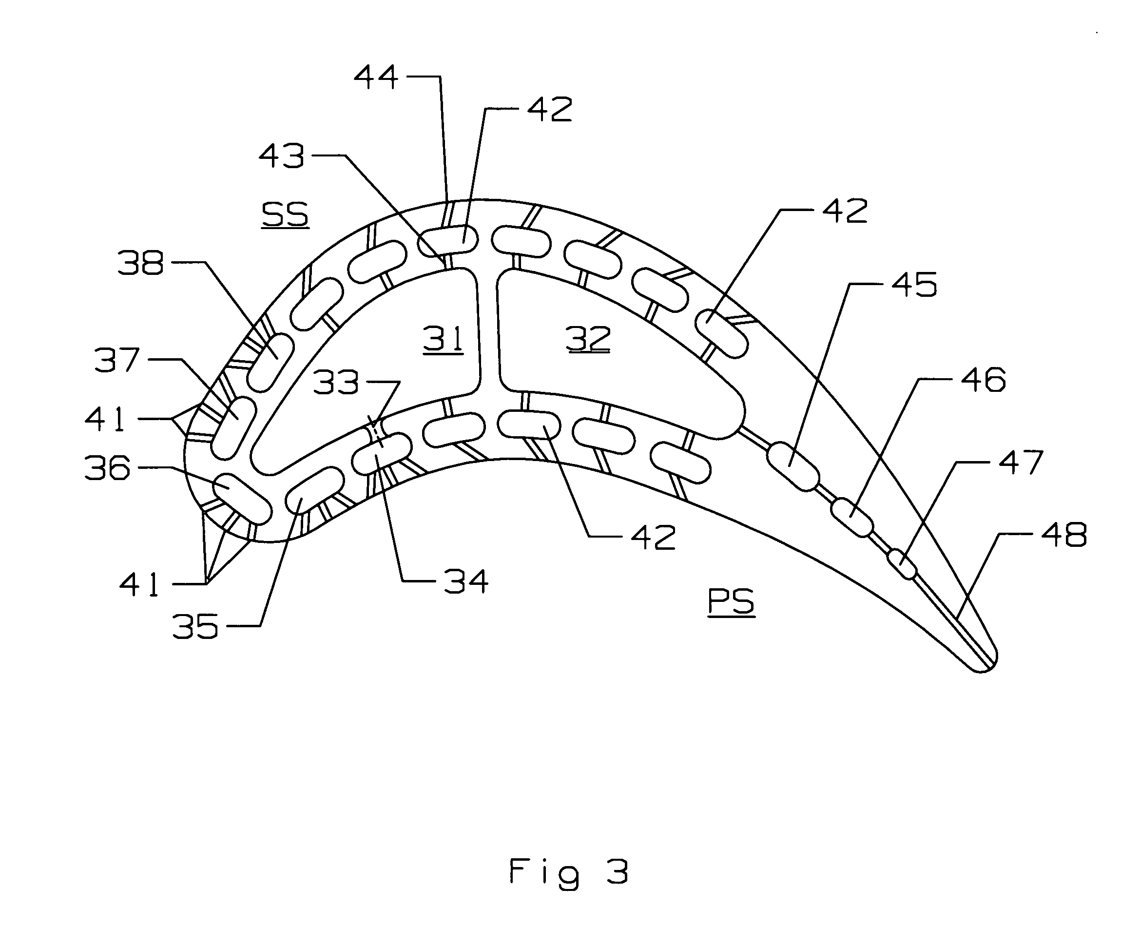
[0019]The air cooled turbine airfoil of the present invention is shown in FIG. 3 in which a cooling supply channel 31 extends along the leading edge of the airfoil to supply cooling air for the leading edge region. A trailing edge cooling supply channel 32 also supplies cooling air to the airfoil to provide cooling for the trailing edge region. Additional cooling supply channels can be included within the airfoil and positioned between the channels 31 and 32 to provide additional cooling capability. Also, the turbine airfoil can be for a rotor blade or a stator vane.

[0020]The present invention includes a series of serpentine flow cooling circuits extending along the leading edge of the airfoil. FIG. 4 shows one embodiment in which the leading edge cooling circuits include 3-pass serpentine flow circuits and FIG. 5 shows them as 5-pass serpentine flow circuits. In FIG. 3, the 5-pass serpentine flow circuits are used. An inlet metering and impingement hole 33 connects the leading edge...


PUM


Abstract

A turbine airfoil with a leading edge cooling air supply channel located along the leading edge region of the airfoil to supply cooling air from an outside source and a series of serpentine flow cooling circuits positioned along the leading edge of the airfoil connected to the cooling supply channel to pass cooling air through the series of serpentine passages in a direction from the airfoil root to the airfoil tip. The series of serpentine circuits includes legs on the pressure side and the suction side of the leading edge. Cooling air from the supply channel is metered into the first leg of the serpentine circuit located near the root, flows through a series of serpentine circuits along the leading edge of the airfoil, and flows out to the tip through a tip hole in the last leg of the last serpentine circuit.

Description

CROSS-REFERENCE TO RELATED APPLICATIONS[0001]This application is related to co-pending U.S. regular application Ser. No. 11 / 503,549 to George Liang filed Aug. 11, 2006 and entitled TURBINE AIRFOIL WITH MINI-SERPENTINE COOLING PASSAGES; and co-pending U.S. Regular application Ser. No. 11 / 508,013 to George Liang filed on Aug. 21, 2006 and entitled TURBINE BLADE TIP WITH MINI-SERPENTINE COOLING CIRCUIT; and to U.S. Regular application Ser. No. 11 / 521,748 to George Liang filed on Sep. 15, 2006 and entitled TURBINE AIRFOIL WITH NEAR-WALL MINI-SERPENTINE LEADING EDGE COOLING PASSAGE; and co-pending U.S. regular application Ser. No. 11 / 903,558 to George Liang filed on Sep. 21, 2007 and entitled TURBINE AIRFOIL WITH NEAR-WALL COOLING, all of which are incorporated herein by reference.BACKGROUND OF THE INVENTION[0002]1. Field of the Invention[0003]The present invention relates generally to fluid reaction surfaces, and more specifically to leading edge cooling of airfoils in a gas turbine eng...

Claims


Application Information

Patent Timeline
IPC IPC(8): F01D5/18
CPCF01D5/187F05D2250/185F05D2260/202F05D2260/22141
Inventor LIANG, GEORGE
Owner FLORIDA TURBINE TECH
Why Eureka
Try Eureka