Steam Turbine Stator Vane and Steam Turbine Using the Same

Active Publication Date: 2012-03-29
MITSUBISHI HITACHIPOWER SYST LTD
View PDF4 Cites 9 Cited by
  • Summary
  • Abstract
  • Description
  • Claims
  • Application Information

AI Technical Summary

Benefits of technology

[0023]According to the present invention, it is possible to improve the flow pattern in the radial direction while the length of the moving blade is increased, suppress a reduction in the degree of reaction in the in

Problems solved by technology

The radial three-dimensional flow causes an increase in a profile loss of the blade and a reduction in the efficiency.
When the len

Method used


Image

  • Steam Turbine Stator Vane and Steam Turbine Using the Same
  • Steam Turbine Stator Vane and Steam Turbine Using the Same
  • Steam Turbine Stator Vane and Steam Turbine Using the Same

Examples


first embodiment

[0035]A first embodiment of the present invention is described below. The present embodiment applies to a last stage of a low-pressure turbine. However, the embodiment is not limited to the last stage of the low-pressure turbine.

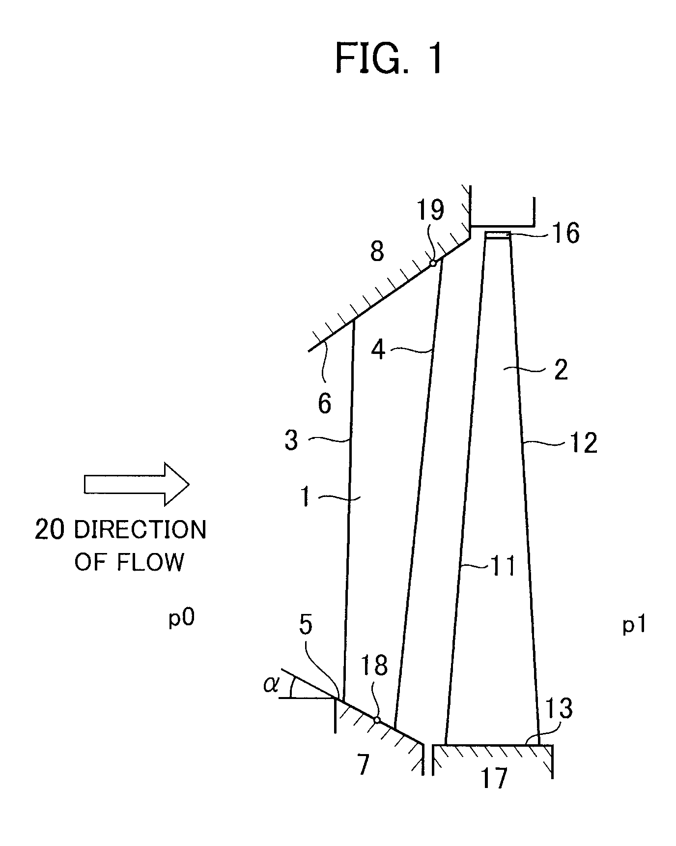
[0036]FIG. 1 is a meridian cross-sectional view of a main structure of a turbine stage according to the present embodiment. As illustrated in FIG. 1, the turbine stage that is included in a steam turbine is located between a high-pressure section p0 arranged on the upstream side (hereinafter merely referred to as upstream side) of flow of a working fluid in a steam passage and a low-pressure section p1 located on the downstream side (hereinafter merely referred to as downstream side) of the flow of the working fluid in the steam passage. The turbine stage includes a stator vane 1 and a moving blade 2. The stator vane 1 is installed and fixed between an outer circumferential side stator vane stationary portion 8 and an inner circumferential side stator vane s...

second embodiment

[0069]Next, a second embodiment of the present invention is described. FIG. 7 is a meridian cross-sectional view of a main structure of a turbine stage according to the second embodiment of the present invention. Constituent elements that are the same as the first embodiment are indicated by the same reference numerals, and a description thereof is omitted. The second embodiment is different from the first embodiment in a change (or axial lean) in the trailing edge curved line of the stator vane in the axial direction of the turbine rotor 17.

[0070]A steam turbine illustrated in FIG. 7 has a stator vane 1B. A curved line 10B is a curved line represented by rotationally projecting a trailing edge curved line of the stator vane 1B on a meridian surface (surface of the turbine rotor taken along the central axis of the turbine rotor (or the surface of the paper sheet of FIG. 7)) of the steam turbine. The curved line 10B is also called a “meridian surface curved line” for convenience. A s...


PUM


Abstract

Suppressing profile loss of a moving blade due to radial flow without an increase in the length of a shaft of a turbine is disclosed. The degree of reaction on an inner circumferential side is set to an appropriate degree, reducing profile loss due to supersonic inflow, and improving turbine efficiency. A steam turbine stator vane has a trailing edge with a curved line when the stator vane is viewed from a downstream side in the axial direction. The curved line has an inflection point located on an outer circumferential side with respect to the center of the stator vane in the height direction of the stator vane. An inner circumferential portion of the curved line is located on the inner circumferential side with respect to the inflection point. An outer circumferential portion of the curved line is located on the outer circumferential side with respect to the inflection point.

Description

BACKGROUND OF THE INVENTION[0001]1. Field of the Invention[0002]The present invention relates to a steam turbine stator vane.[0003]2. Description of the Related Art[0004]In general, a steam turbine has a plurality of stages that are each constituted by stator vanes and moving blades, while the stages are arranged in the axial direction of a turbine rotor. An exhaust hood is installed on the downstream side of the steam turbine. Steam that is a working fluid is accelerated by stator vanes that serve as a convergent passage so that kinetic energy of the steam is increased. The kinetic energy is converted into rotational energy by moving blades so that power is generated.[0005]In the steam turbine, when the lengths of the turbine blades located at a last stage of a low-pressure turbine are increased, the area of a passage through which steam flows is increased, and the kinetic energy of the steam is reduced. Thus, kinetic energy that is not used for generation of power and is exhausted...

Claims


Application Information

Patent Timeline
IPC IPC(8): F01D9/02F04D21/00F01D1/02
CPCF01D5/141F05D2220/31F05D2250/713F05D2240/122F05D2250/711F05D2240/121
Inventor ONO, HIDEKIMURATA, KENICHISENOO, SHIGEKI
Owner MITSUBISHI HITACHIPOWER SYST LTD
Why Eureka
Try Eureka