Steam Micro Turbine Engine

Inactive Publication Date: 2016-08-25
CHEN JACK YAJIE
View PDF0 Cites 0 Cited by
  • Summary
  • Abstract
  • Description
  • Claims
  • Application Information

AI Technical Summary

Benefits of technology

The present invention aims to improve the efficiency and reduce the complexity of gas micro turbines by using steam as the primary working medium instead of atmospheric air. This is achieved by controlling the temperature in the combustion chamber to minimize waste heat and reduce NOx pollution. The lower operating temperature also reduces the requirements for expensive turbine blades and bearing materials. In certain embodiments, injection water heat exchange occurs through conduits in the combustion chamber wall to simplify manufacturing process and further more prevent thermal energy from releasing into surrounding environment.

Problems solved by technology

During this process, a huge amount of waste heat is generated and released into the atmosphere.
It increases the size of the generator system and the total cost of the gas turbine.
Although micro turbine engines have a great power-to-weight ratio and are small in size compared to internal combustion reciprocating engines, they have not been used in small applications like motorized vehicles, household emergency electric generators except in large applications like jet airplanes and power plants.
The prior arts are not able to address the tough problem in designing and manufacturing gas turbines from both the engineering and materials standpoint because of the high operating temperatures.
High combustion temperature in a gas turbine engine also causes Nitric Oxides emission and reduces turbine blade working life.
Strict material requirements to withstand higher temperature and pressure contribute to higher design and fabrication cost.
When the turbine engine is used in automotive applications, it is harder to control the dynamic of the overall output to follow fluctuating load.
Lower operating temperature also reduces the requirements for turbine blades and bearing materials, which are big obstacles, in terms of cost, of applying turbine technology in small application such as motorized vehicles and portable electric generators.

Method used


Image

  • Steam Micro Turbine Engine
  • Steam Micro Turbine Engine
  • Steam Micro Turbine Engine

Examples


Embodiment Construction

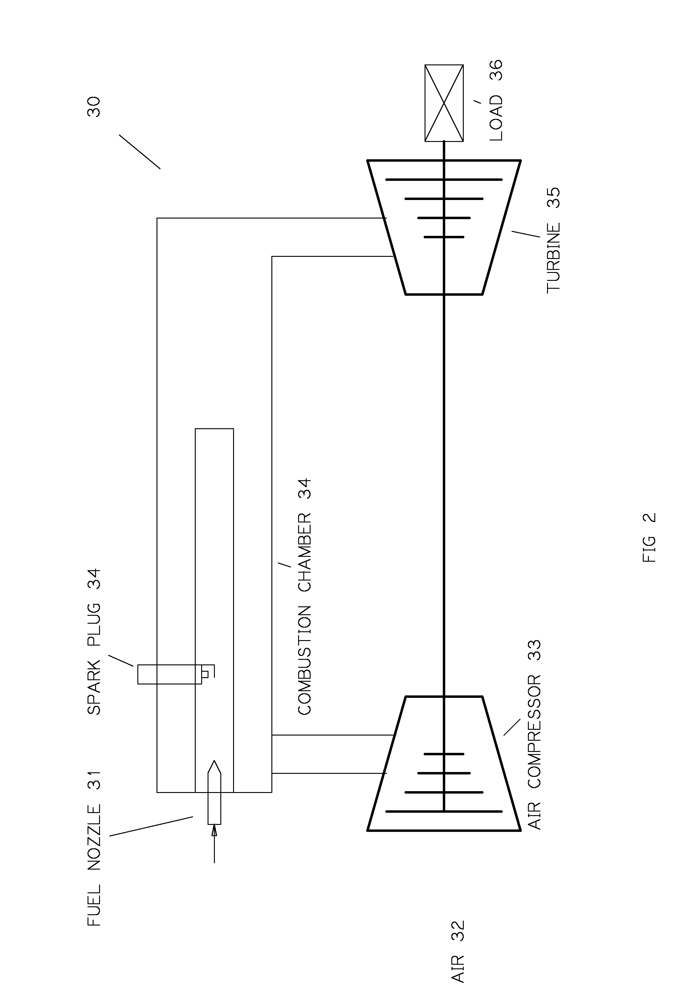
[0023]With reference to FIG. 2, a traditional micro turbine engine 30 comprises of air compressor 33, combustion chamber 34, turbine 35, spark plug 34 and fuel nozzle 31. A fresh air steam is compressed by the compressor 33 and enters into combustion chamber 34. It is mixed with the fuel injected by fuel nozzle 31. The spark plug 34 ignites the air-fuel mixture. The mixture is heated by energy released by the chemical reaction in the burn process and expanding with higher volume and velocity. This exhaust gas flows through turbine to extract energy for useful mechanical work.

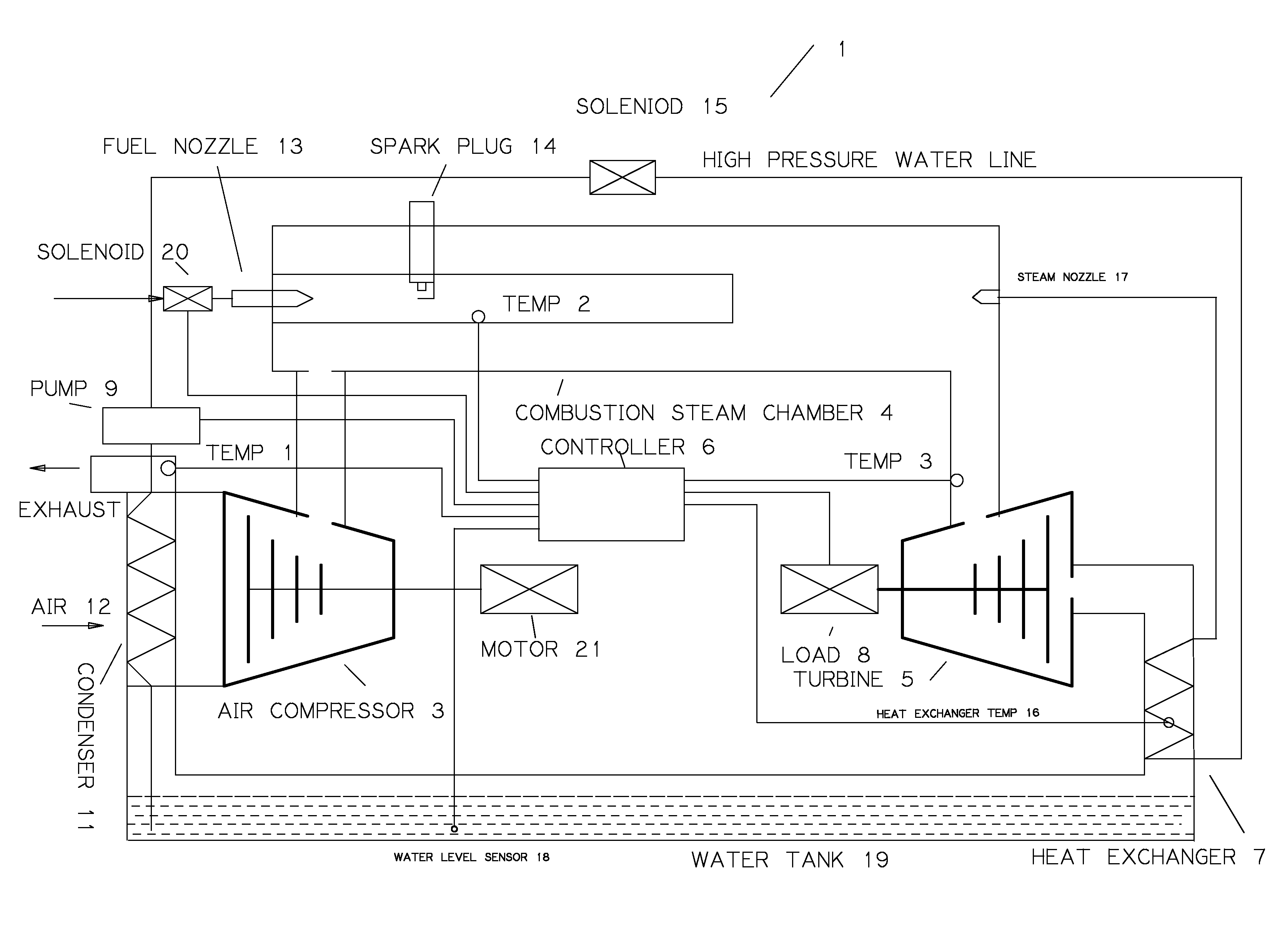
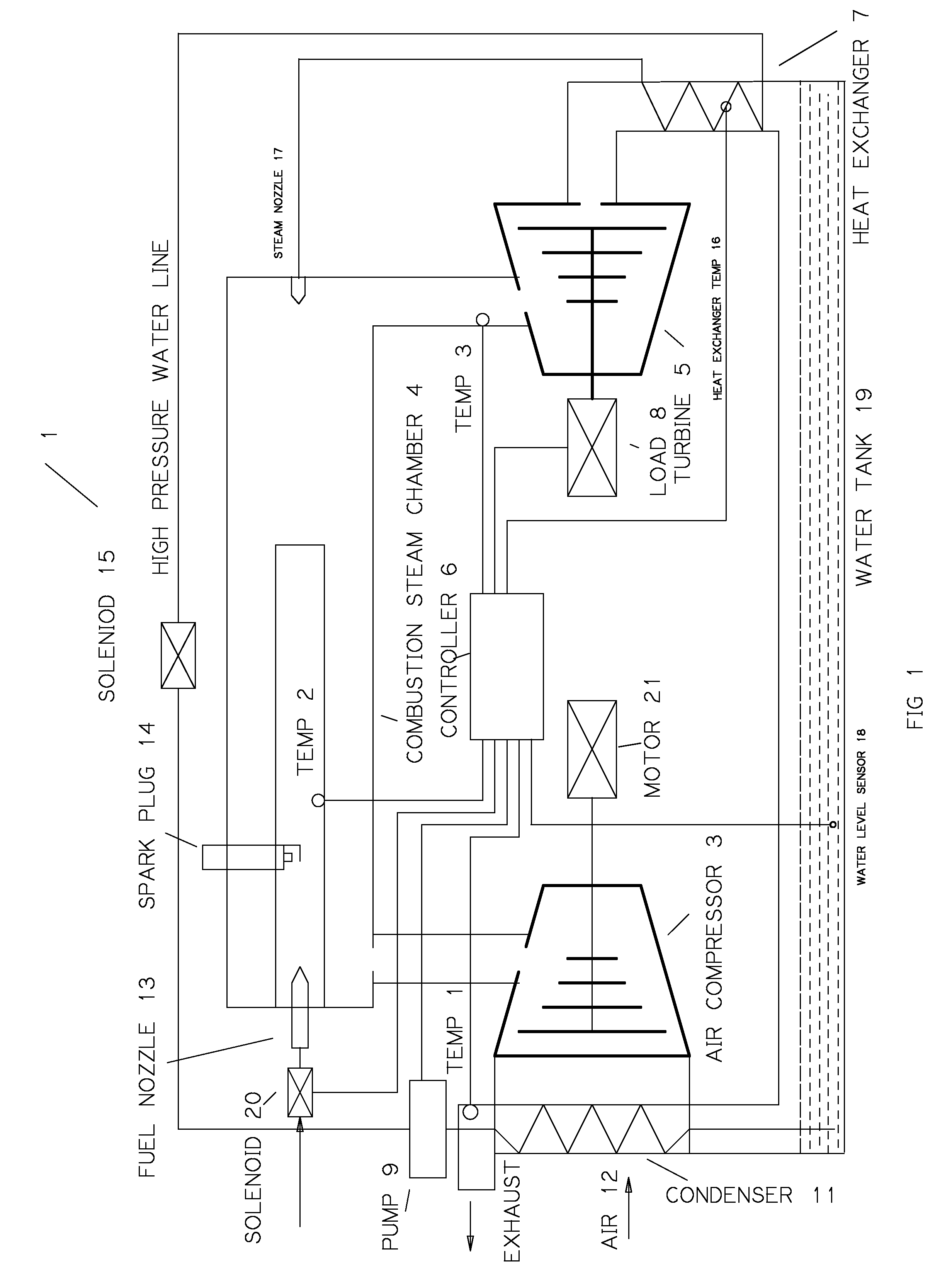
[0024]With reference to FIG. 1, a steam micro turbine engine 1 in accordance to an aspect of the present disclosure comprises of air compressor 3, combustion steam chamber 4, turbine 5, controller 6, water heat exchange 7, water pump 9, spark plug 14, water solenoid 15 and fuel nozzle 13.

[0025]A fresh air stream is heated by a condenser 11 and flows through into the compressor 3. The compressed heated air enters...


PUM


Abstract

A steam micro turbine engine is improved from a conventional micro turbine engine by injecting small amount of near boiling temperature water into combustion chamber after the fuel is partially burned and gas mixture temperature raises well above boiling point. A steam micro turbine engine controller monitors the temperature of the engine, adjusts fuel and water injection amount. The apparatus can reduce fuel consumption and emission by taking advantage of the waste heat and turning water into steam to generate extra useful work. This steam micro turbine engine could reach 60% efficiency instead of 30% in existing micro turbine engine. This engine can be used in household furnace electric co-generation systems, series hybrid electric vehicles and portable electric generators since its size is small with simplified components, relatively low operating temperature and much lower cost than traditional micro turbine engine.

Description

BACKGROUND[0001]1. Field of the Invention[0002]This disclosure relates to improved gas micro turbine engine, wherein water is injected into the combustion chamber to maintain preset exhaust temperature for maximized efficiency with minimum waste heat. The burning air-fuel mixture evaporates the injection water into steam, thereby creating extra pressure to drive the turbine for useful work.[0003]2. Description of Related Art[0004]Over the past one hundred years, gas turbine engine has been the major power source for aviation apparatus, ships, locomotives, helicopters, and power plants. Industrial gas turbines usually have fewer moving part than internal combustion reciprocating engines found in most of the motorized vehicles. As the result, gas turbines are more reliable and more efficient. Their efficiency ranges from 35% to 90% in co-generation configuration. However, internal combustion engines (ICE) have been dominated in the small application area, like motorized vehicles, emer...

Claims


Application Information

Patent Timeline
IPC IPC(8): F01K7/16F01K9/00
CPCF01K9/003F01K7/16F01K21/047
Inventor CHEN, JACK YAJIE
Owner CHEN JACK YAJIE
Why Eureka
Try Eureka