Pin-style collector brush holder with rotating spring plate, radial contact, and brush-wear indicator

a technology of spring plate and collector, which is applied in the direction of current collectors, dynamo-electric machines, supports/encloses/casings, etc., can solve the problems of affecting the operation of commercial electric generators, and affecting the operation of electric generators

Inactive Publication Date: 2011-11-01
GENERAL ELECTRIC CO
View PDF17 Cites 9 Cited by
  • Summary
  • Abstract
  • Description
  • Claims
  • Application Information

AI Technical Summary

Problems solved by technology

As the brushes are stationary with respect to the rotating elements, the brushes, which are made of carbon, wear due to friction and need periodic replacement.
Commercial electric generators are expensive to operate and need to generate revenue to support operations.
Using two hands increases the probability of an accident with current flowing from one hand to another hand through the operator's body.
For example, one type of brush holder weighs about ten pounds making it difficult for the operator to change out using only one hand.
There are both ergonomic and safety concerns with this design.
Also, while the brush surfaces are exposed to cooling air, it is difficult to see the amount of brush wear in order to determine an appropriate time for brush replacement.
As another example, other brush holders are somewhat lighter at five pounds but still too heavy to be conveniently changed out with only one hand.
These brush holders are generally complicated and expensive.
Unfortunately, the box-style enclosure limits the amount of brush surface exposed to cooling air, thus, shortening the life span of the brush.
In addition, it is difficult to see the amount of brush wear using the box-style enclosure design.
One box-style holder design uses a wear indicator attached to each individual brush, increasing the cost of each brush and, therefore, maintenance costs.

Method used


Image

  • Pin-style collector brush holder with rotating spring plate, radial contact, and brush-wear indicator
  • Pin-style collector brush holder with rotating spring plate, radial contact, and brush-wear indicator
  • Pin-style collector brush holder with rotating spring plate, radial contact, and brush-wear indicator

Examples


Embodiment Construction

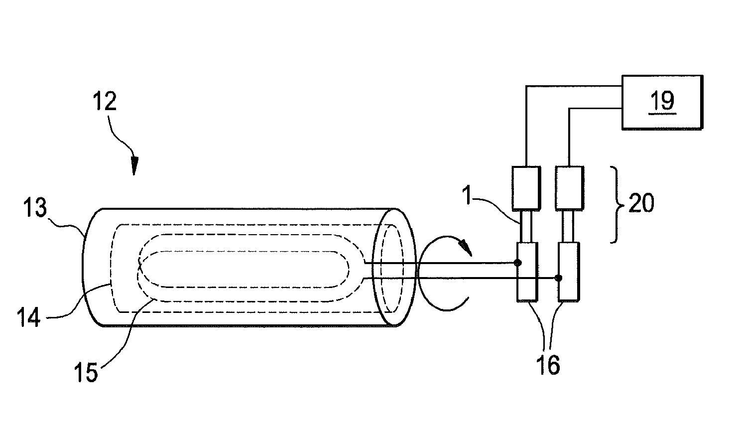
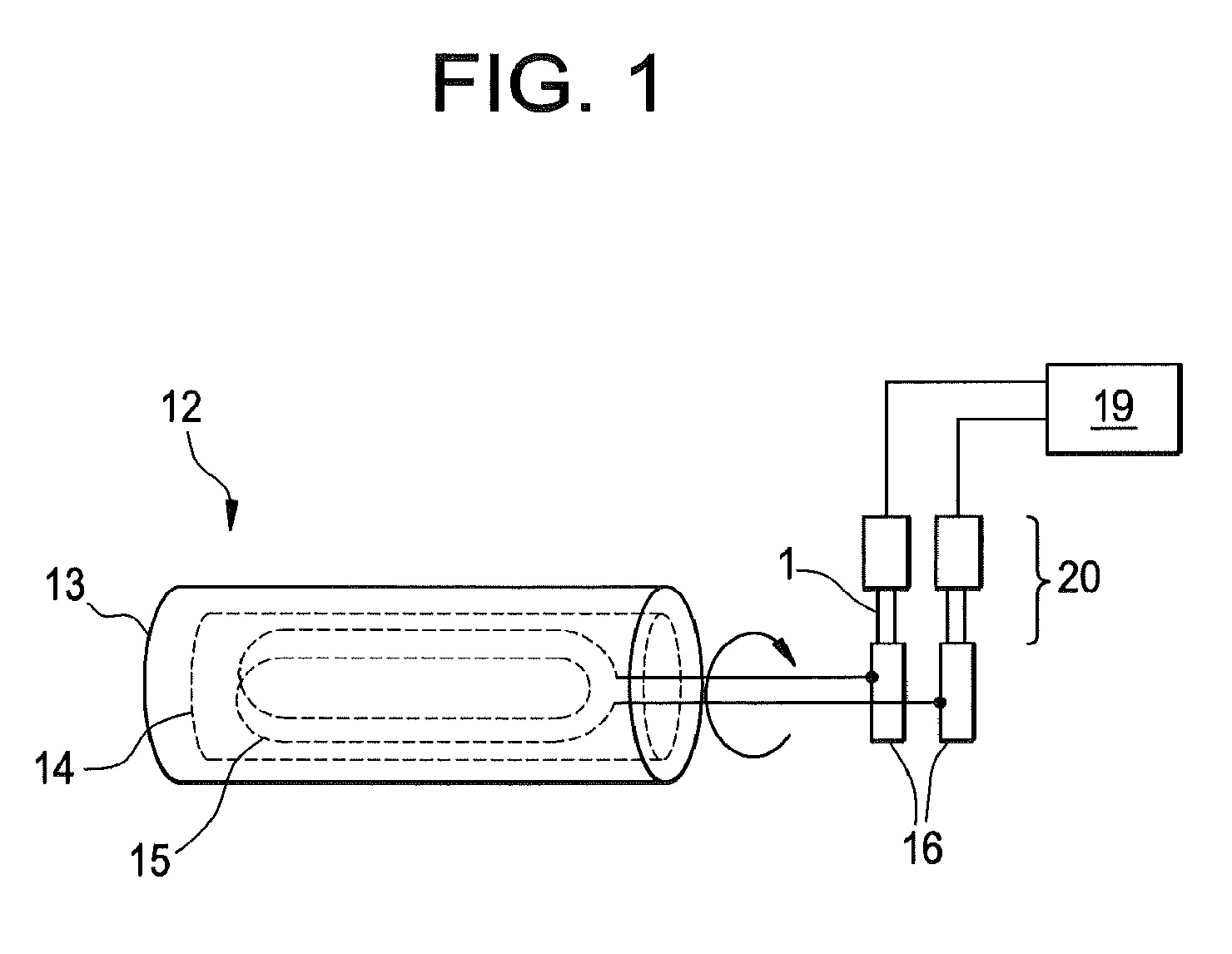
[0023]Disclosed are techniques that allow changing brushes in a dynamoelectric machine safely, quickly, and inexpensively while the machine is operational. The techniques, which include apparatus and method, call for a brush holder assembly that is lightweight at approximately two and a half pounds in one embodiment. The lightweight allows an operator to lift and install the brush holder assembly without struggling due to heavy weight. In addition, the lightweight allows for more precise handling and positioning of the brush holder assembly resulting in increased safety.

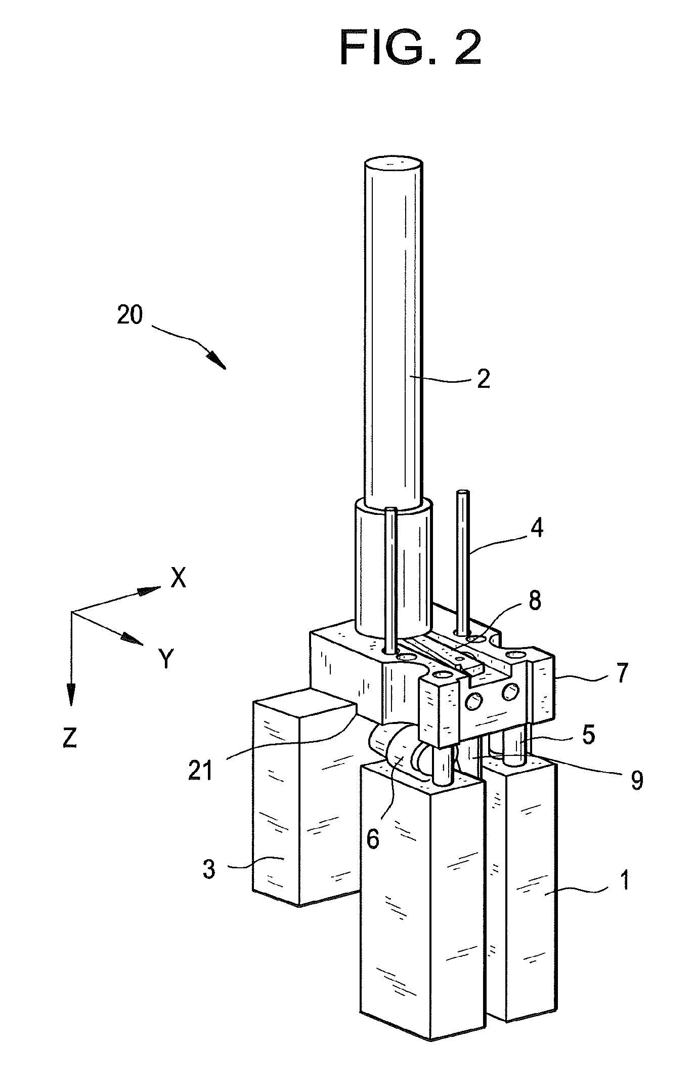
[0024]The brush holder assembly includes features designed to make the brush change out quick and inexpensive. One feature provides an interface between the brush holder assembly and the machine that quickly secures the brush holder to the machine with a turn of a removable handle. Besides securing the brush holder assembly to the machine, turning the handle also releases the brushes to allow them to make contact wit...


PUM


Abstract

An apparatus for holding a brush in contact with a moving conductive surface, the apparatus includes: a rotatable member disposed adjacent to the brush; and a spring coupled to the brush and to the member and configured to bias the brush towards the moving conductive surface; wherein the rotatable member in a first position makes contact with the brush to secure the brush from movement and in a second position releases the brush from the contact to allow the spring to hold the brush in contact with the moving conductive surface.

Description

BACKGROUND OF THE INVENTION[0001]The present invention relates to a brush holder assembly for conducting electrical current between a brush and a rotating element of a dynamoelectric machine. In particular, the brush holder assembly can be replaced during operation of the machine.[0002]A dynamoelectric machine has a rotor with windings that conduct electrical current for operation of the machine. Because the rotor rotates, rotating elements are used to conduct current to the rotor windings from a source external to the rotor. The rotating elements such as collector rings or commutators make contact with brushes to conduct the current. As the brushes are stationary with respect to the rotating elements, the brushes, which are made of carbon, wear due to friction and need periodic replacement.[0003]Commercial electric generators are expensive to operate and need to generate revenue to support operations. Hence, a major goal in operating the generator is to reduce downtime for maintena...

Claims


Application Information

Patent Timeline
Patent Type & Authority Patents(United States)
IPC IPC(8): H02K15/00H02K13/00
CPCH01R39/40H01R43/14H02K5/14H02K13/10
Inventor QUAIL, PAUL AUGUSTSTEINBACH, ALBERT EUGENE
Owner GENERAL ELECTRIC CO
Why Eureka
Try Eureka