
Hardware compensating pulse compression filter system and method

a filter system and filter technology, applied in the field of hardware compensating pulse compression filter system and method, can solve the problems of increased integrated or peak range side lobe level and other amplitude and phase distortion, difficulty in the system to correlate the transmitted/received signal to the reference waveform, and high cost of design and manufacture. achieve the effect of improving the resolution of the signal

Active Publication Date: 2011-11-01
RAYTHEON CO
View PDF4 Cites 58 Cited by
  • Summary
  • Abstract
  • Description
  • Claims
  • Application Information

AI Technical Summary

Problems solved by technology

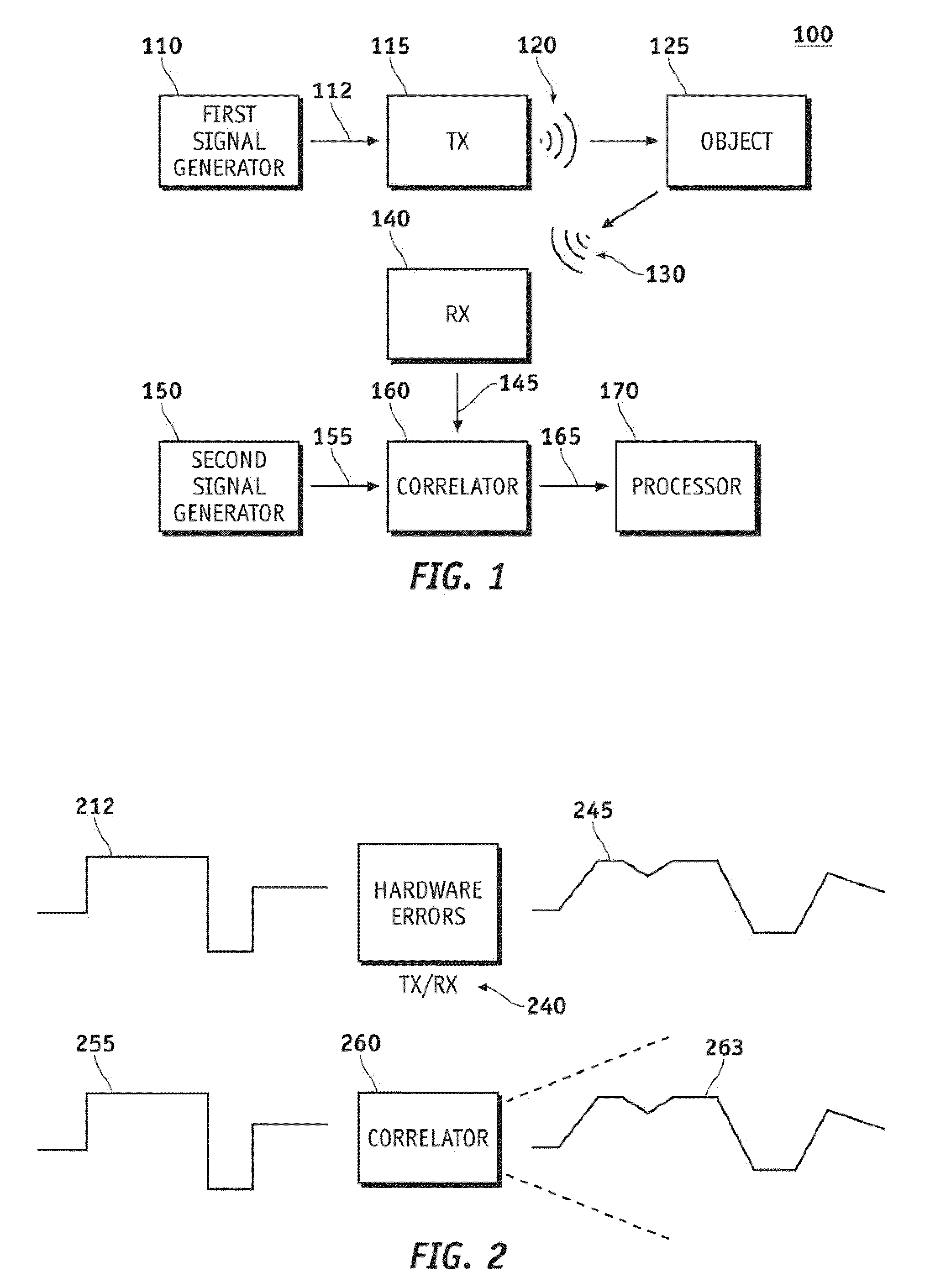
This degradation may manifest itself in terms of increased integrated or peak range side lobe levels and other amplitude and phase distortions.
The degradation further results in difficulty by the system to correlate the transmitted / received signal to the reference waveform.
To compensate for this problem, radar hardware generally had to be very carefully designed and manufactured to remove the inherent hardware impairments, which is very costly to design and manufacture.

Method used


Image

  • Hardware compensating pulse compression filter system and method
  • Hardware compensating pulse compression filter system and method
  • Hardware compensating pulse compression filter system and method

Examples


Embodiment Construction

[0014]The descriptions contained are of exemplary embodiments of the invention and the inventor's conception of the best mode and are not intended to limit the scope, applicability or configuration of the invention in any way. Rather, the following description is intended to provide convenient illustrations for implementing various embodiments of the invention. Changes may be made in the function and / or arrangement of any of the elements described in the disclosed exemplary embodiments without departing from the spirit and scope of the invention.

[0015]Various representative implementations of the hardware compensating pulse compression filter system and method may be applied to any radar system. Certain representative implementations may include, for example: a hardware compensating pulse compression filter sized suitably for any pulse-coded system; made out of any suitable material and / or the like. The hardware compensating pulse compression filter system and method may provide an ...


PUM


Abstract

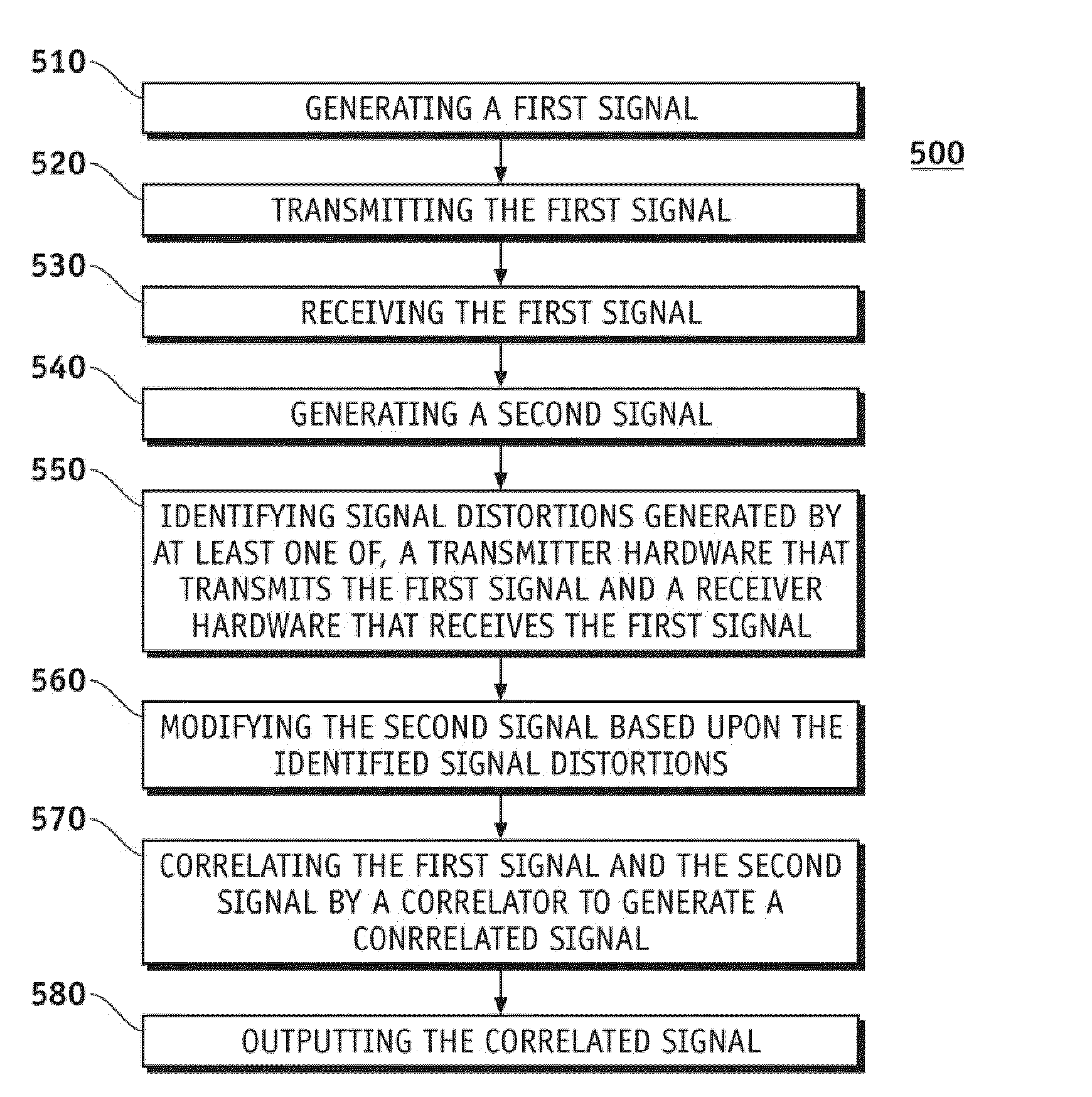
A method to improve a system's signal performance may comprise: generating a first signal, transmitting the first signal, receiving the first signal, and generating a second signal. The method may further comprise: identifying signal distortions generated by at least one of, a transmitter hardware that transmits the first signal and a receiver hardware that receives the first signal, modifying the second signal based upon the identified signal distortions, correlating the first signal and the second signal by a correlator to generate a correlated signal, and outputting the correlated signal.

Description

CROSS-REFERENCES TO RELATED APPLICATIONS[0001]This application claims the benefit of U.S. Provisional Patent Application No. 61 / 055,123 filed May 21, 2008, and incorporates the disclosure of that application by reference.FIELD OF INVENTION[0002]A hardware compensating pulse compression filter system and method is generally directly towards a system and method to improve a signal's resolution. More particularly, embodiments of a hardware compensating pulse compression filter system and method generally relate to systems, devices, and methods for reducing the effects of radar signal degradation caused by the system's hardware.BACKGROUND OF INVENTION[0003]A pulsed Doppler radar system that may be used to determine a detected object's range relies upon a signal, such as a compressed waveform. The signal is transmitted and received back by the radar system; i.e. the compressed waveform echoes back from contact with the detected object. The received signal is then correlated against a ref...

Claims


Application Information

Patent Timeline
Patent Type & Authority Patents(United States)
IPC IPC(8): G01S7/40
CPCG01S7/4004G01S13/28G01S13/53
Inventor FRANK, MARK S.RUPP, MARTY K.PRATT, DEVIN B.
Owner RAYTHEON CO
Learn More