Decelerated centrifugal dust removing apparatus for dust cleaner

a technology of centrifugal dust removal and dust cleaner, which is applied in the direction of filtration separation, auxillary pretreatment, separation processes, etc., can solve the problems of bringing trouble to the user, motor burnout, and structure of the conventional dust cleaner having some defects

Inactive Publication Date: 2003-10-30
SUZHOU KINGCLEAN FLOORCARE
View PDF13 Cites 104 Cited by
  • Summary
  • Abstract
  • Description
  • Claims
  • Application Information

AI Technical Summary

Problems solved by technology

If the blockage is serious, even the motor will be burned out.
So, the structure of the conventional dust cleaner has some defects, which not only may bring trouble to the user, but also may affect the operating performance of the dust cleaner.
Besides, the accelerated air stream tends to lift again fine dust already falling into the bottom, and this fine dust will go out from the air outlet pipe together with air flow, resulting in the secondary pollution of the cleaned air.
In addition, the apparatus mentioned above is rather suitable for the separation of larger size dust particles, for small-size dust separation, its effect is not ideal.
1. Because the conical cylinder has the shape of small upper end and large lower end, the rotation of the air flow in the conical cylinder will be in a decelerated centrifugal state, so the loss of air flow pressure will be small, therefore the effect of air suction of dust cleaner will be ensured.
2. As the rotation speed of air in the lower part of the conical cylinder is smaller than that in the upper part, dust in the bottom of the dust collecting box will not...

Method used


Image

  • Decelerated centrifugal dust removing apparatus for dust cleaner
  • Decelerated centrifugal dust removing apparatus for dust cleaner
  • Decelerated centrifugal dust removing apparatus for dust cleaner

Examples


Embodiment Construction

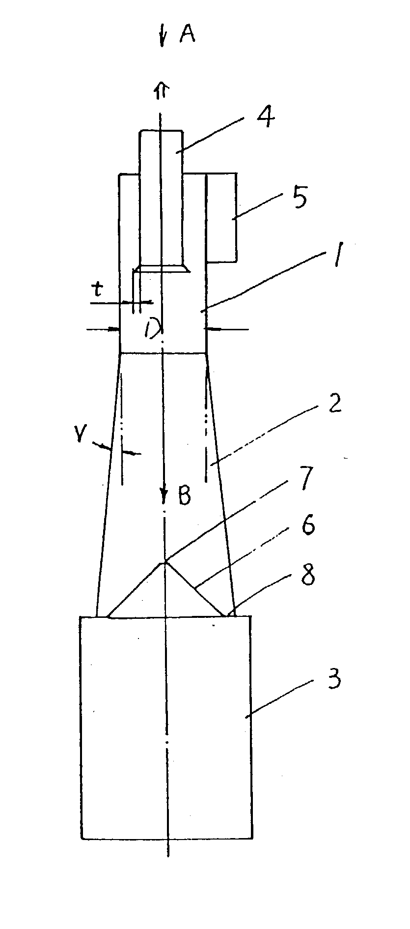
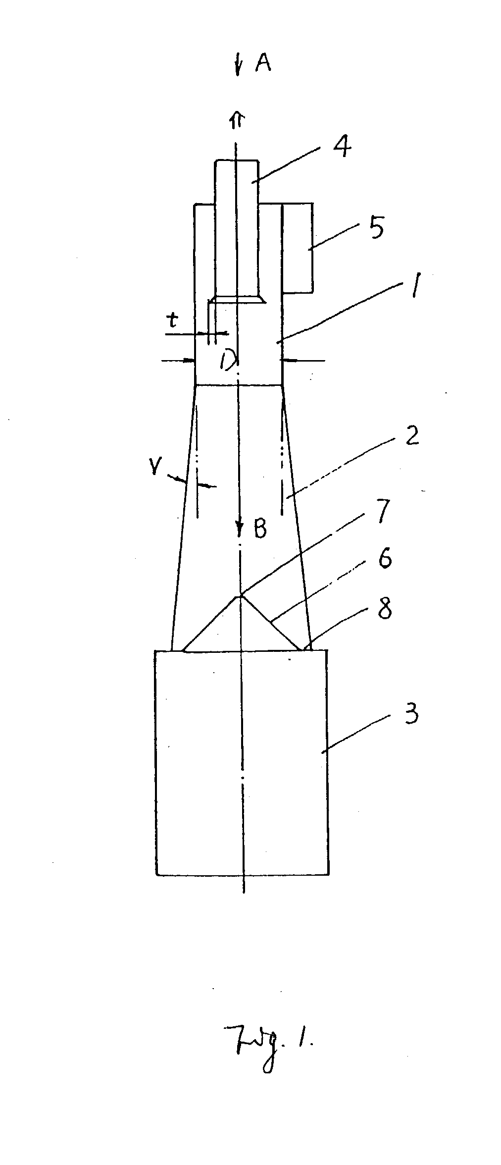
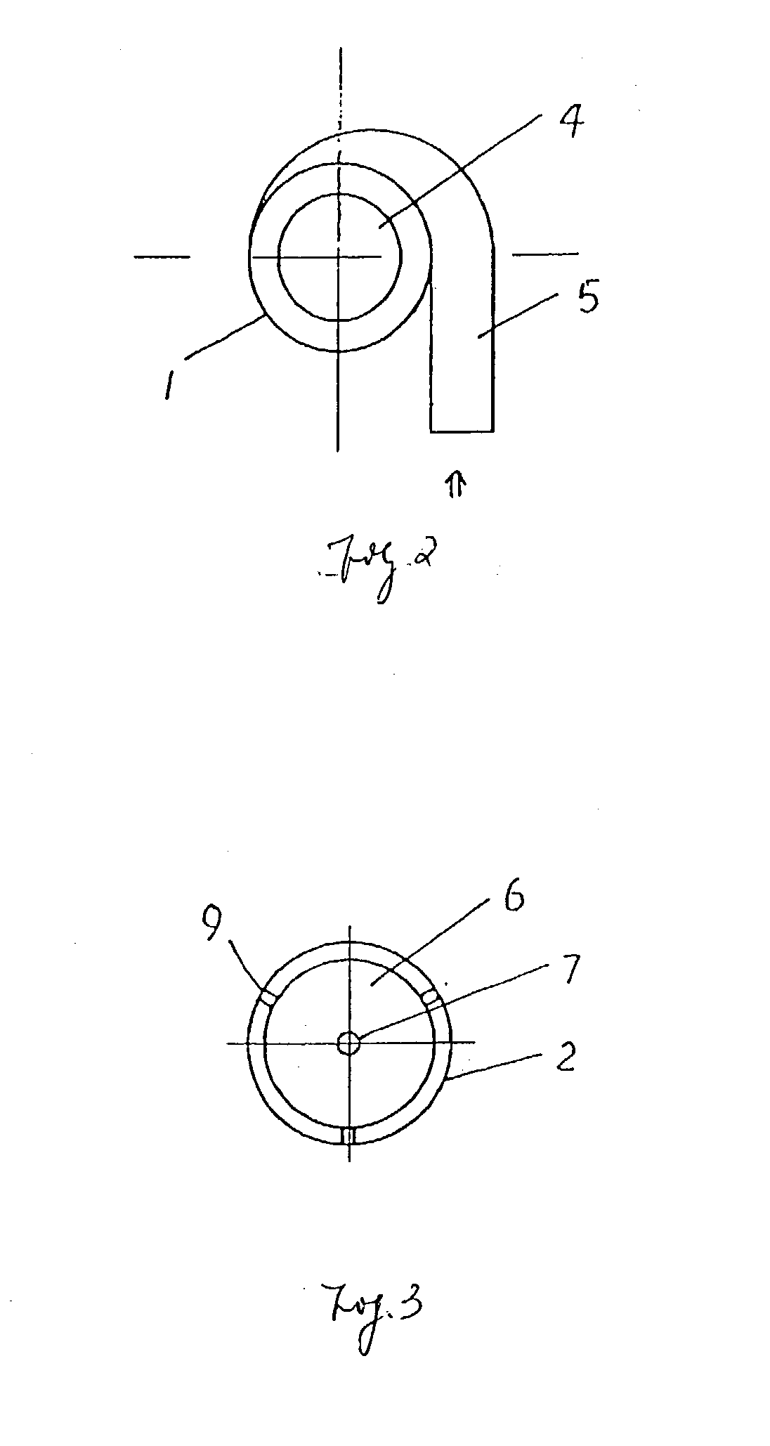
[0025] An exemplary embodiment of the invention is shown in FIG. 1., FIG. 2, and FIG. 3. It is a decelerated centrifugal dust removing apparatus for use with a dust cleaner. It comprises a cylinder 1, a conical cylinder 2 and a dust collector box 3 connected one after another in the given order sequentially from the top to the bottom. On the top of the cylinder, an air outlet pipe 4 is disposed along the axis. The air outlet pipe 4 extends downwardly into the cylinder 1, the lower end of the air outlet pipe 4 has a flared shape. There is an air inlet pipe 5 connected on the outer side wall of the cylinder 1, and the air inlet pipe 5 goes around the cylinder / at least 90.degree. of air of a circle before it enters into the cylinder 1. The conical cylinder 2 has a small upper end and a large lower end. The range of the optimum conical angle V is 5.degree.-60.degree.. An umbrella-shaped reflector (reflecting disc) 6 is provided in the lower part of the conical cylinder 2. There is an an...


PUM

PropertyMeasurementUnit
Angleaaaaaaaaaa
Angleaaaaaaaaaa
Diameteraaaaaaaaaa

Abstract

The present invention discloses a decelerated centrifugal dust removing apparatus for a dust cleaner. It comprises a cylinder, a conical cylinder and a dust collector box connected in the given order from the upper part to the lower part, as well as an air outlet pipe and an air inlet pipe on the cylinder body. The conical cylinder has a small upper end and a large lower end. In the conical cylinder, on the lower part of the air outlet pipe (under the air outlet pipe) there is an umbrella-shaped reflector in the center of which is provided a hole for air returning. Between the periphery of the umbrella reflector and the side wall is provided an annular gap for the falling down of dust. The apparatus features small loss of air flow pressure, good effectiveness of air suction, high quality of dust filtering, and low noise. With the apparatus, the secondary pollution of the cleaned air can be effectively prevented, and it is especially suitable for use in a secondary stage filtering system of the dust cleaner and for separating small and fine dust particles.

Description

CLAIM FOR PRIORITY TO RELATED APPLICATIONS[0001] This application claims the benefit of China Patent Application serial no. CN 02112963.0, filed on Apr. 28, 2002, which is hereby incorporated by reference in its entirety herein.1. TECHNICAL FIELD[0002] The present invention relates to a decelerated centrifugal dust removing apparatus for a dust cleaner.2. BACKGROUND[0003] Nowadays, dust cleaners are usually equipped with a filtering cover or a dust collecting bag, in order to filter dirty air sucked in by vacuum generating motor, and to let the dust particles stay in the dust collection cylinder or dust collecting bag. When the dust cleaner has been used for a certain period of time, the user should clean the filtering cover or dust collecting bag or replace it. Otherwise, after the filtering holes of the filtering cover or dust collecting bag have been blocked by fine dust particles, the vacuum generating motor will encounter higher resistance in sucking dust. If the blockage is se...

Claims


Application Information

Patent Timeline
IPC IPC(8): B01D45/16B04C5/181
CPCB04C5/181B01D45/16
Inventor NI, ZUGEN
Owner SUZHOU KINGCLEAN FLOORCARE
Why Eureka
Try Eureka