Easy maintenance sensing type automatic faucet

a technology of automatic faucet and sensing type, which is applied in the field of faucets, can solve the problem that the easy maintenance structure cannot be applied to the sensing type automatic faucet, and achieve the effect of easy maintenan

Active Publication Date: 2011-11-08
LIN MING SHUAN
View PDF8 Cites 44 Cited by
  • Summary
  • Abstract
  • Description
  • Claims
  • Application Information

AI Technical Summary

Benefits of technology

[0006]The object of this invention is to provide an easy maintenance sensing type automatic faucet.

Problems solved by technology

However, such an easy maintenance structure cannot be applied to a sensing type automatic faucet, such as a position sensing faucet, since an electromagnetic valve, a sensor, and water seals used for waterproofing of the electromagnetic valve and the sensor are difficult to be mounted therewithin.

Method used


Image

  • Easy maintenance sensing type automatic faucet
  • Easy maintenance sensing type automatic faucet
  • Easy maintenance sensing type automatic faucet

Examples


Embodiment Construction

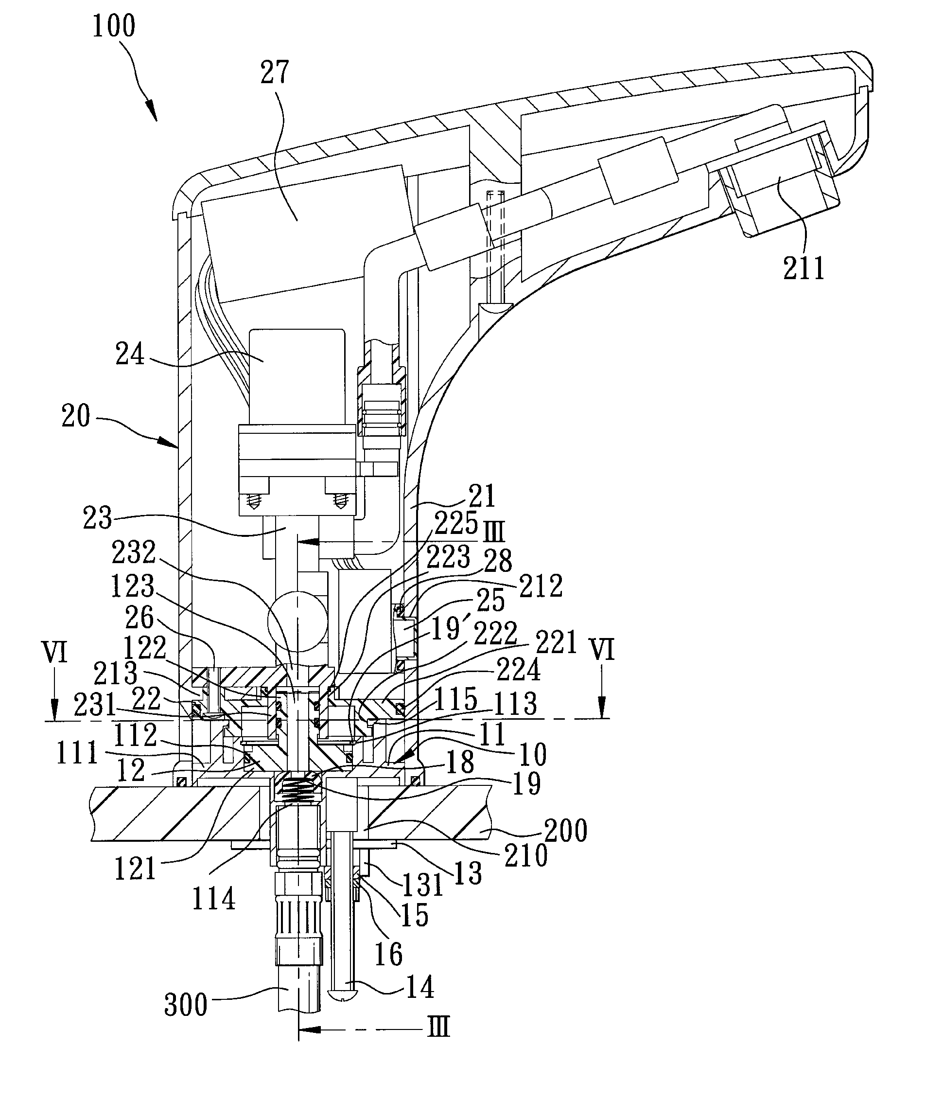
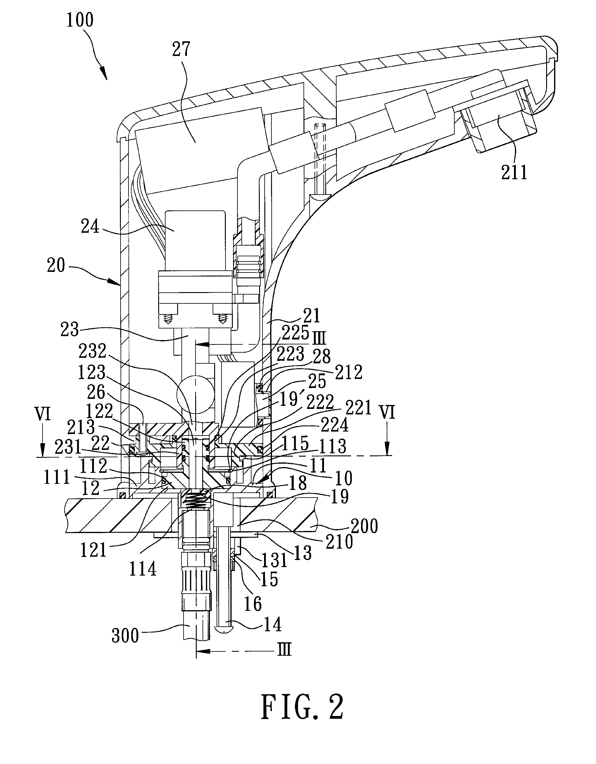
[0016]Referring to FIGS. 2, 3, and 4, an easy maintenance sensing type automatic faucet 100 according to this invention is mounted to a deck 200, and is communicated fluidly with a water source (not shown) by two conduits 300. The deck 200 has a mounting hole 210. The faucet 100 includes a mounting unit 10, a valve unit 20, and a lock unit configured as a lock bolt 216. The mounting unit 10 is disposed on the deck 200, and is aligned with the mounting hole 210. The mounting unit 10 includes a fixed seat 11, a rotatable seat 12, a lower plate 13, a first bolt 14, a positioning plate 15, a nut 16, two second bolts 17, two rubber caps 18, two resilient members 19, and a C-shaped retaining ring 19′. The fixed seat 11 includes an upper plate 111, a recess 112 formed in a top surface of the upper plate 111, a groove 113 formed in an inner surface, two water-guiding holes 114 having lower ends respectively in fluid communication with the conduits 300 and upper ends in fluid communication w...


PUM


Abstract

A faucet includes a mounting unit and a valve unit. The mounting unit includes a fixed seat and a rotatable seat rotatable relative to the fixed seat. The fixed seat is formed with a plurality of inverted L-shaped retaining hooks. The valve unit includes a housing, a coupling member disposed in the housing, a valve seat, an electromagnetic valve, and an infrared sensor. The coupling member includes a plurality of L-shaped retaining grooves engaging respectively the retaining hooks. The retaining hooks can be removed from the retaining grooves to allow for maintenance and replacement of the valve unit.

Description

BACKGROUND OF THE INVENTION[0001]1. Field of the Invention[0002]This invention relates to a faucet mounted on a deck, and more particularly to an easy maintenance faucet that can be removed easily from a deck.[0003]2. Description of the Related Art[0004]Referring to FIG. 1, an easy maintenance faucet disclosed in French Patent Number FR2835005 B1 includes a fixed member 1, a valve block 2 rotatable on the fixed member 1, a valve body unit 3, and a bolt 4. The valve body unit 3 includes a bottom housing 301 covering and attached fixedly to the fixed member 1 by the bolt 4, a valve seat 302 fixed on the bottom housing 301, a connecting member 303 disposed in the valve seat 302 and co-rotatable with the valve block 2, a controlling member 304 disposed in the valve seat 302, and a lever 305 operable to activate the controlling member 304. The housing 301 can be removed easily from the fixed member 1 by removing the bolt 4 to allow for maintenance and replacement of the valve block 2 and...

Claims


Application Information

Patent Timeline
Patent Type & Authority Patents(United States)
IPC IPC(8): E03C1/05
CPCE03C1/04E03C1/057Y10T137/87579
Inventor LIN, MING-SHUAN
Owner LIN MING SHUAN
Why Eureka
Try Eureka