Pan inverting and/or cleaning system

a cleaning system and inverter technology, applied in the field of pan inverter system, can solve the problems of transferring the load of a stacked pile of pans, the inability to move the pans, and the risk of dirt or other unwanted materials falling into the recesses of the pan, so as to improve the inverter and/or cleaning system

Active Publication Date: 2011-11-15
REXFAB
View PDF14 Cites 4 Cited by
  • Summary
  • Abstract
  • Description
  • Claims
  • Application Information

AI Technical Summary

Benefits of technology

[0010]There is therefore provided, in accordance with one aspect of the present invention, a pan inverting system comprising: a rotating table having substantially parallel pan-receiving surfaces on opposite sides of the table, the pan-receiving surfaces having longitudinally spaced apart inlet and outlet ends between which a pan is displaceable, the table being rotatably mounted within a static frame for rotation about a longitudinally extending axis of rotation; a conveyor disposed on each of said pan-receiving surfaces of the table, each said conveyor being independently operable to displace pans along the corresponding pan-receiving surface in a direction substantially parallel to said longitudinally extending axis of rotation; and a pan engagement mechanism disposed within the table and operable to releasably fasten the pans to either of said pan receiving surfaces of the table when the pans are disposed thereon, such that when the pans are fastened to one of the pan receiving surfaces by the pan engagement mechanism, rotation of the table about the longitudinally extending axis will invert the pan.

Problems solved by technology

However, if the pans are stacked on top of each other in a right-side up direction (i.e. with the interior surfaces which receive the bread dough therein facing upwards), then at least the upper most pan is exposed to the environment for a period of time, thus risking that dirt or other unwanted material falls into the recesses of the pan.
Further, when stacked on top of each other a right-side up direction, the load of a stacked pile of pans is transmitted through the more delicate inner surfaces of the pans rather than the more robust and reinforced edge regions, which is not the case when stacked in an upside down orientation.
This process of inverting the pans twice can be quite time consuming with currently employed pan inverting systems, and in a continuous and high-volume production setting, any pan inverting system employed must be able to accommodate a very high throughput which is now required in most modern commercial bakeries, such as a throughput of 30 or more pans per minute.
Thus, while there have been various previous attempts to provide pan inverting systems, there are disadvantages associated with these known systems.
One disadvantage with these types of systems is that the pan loading and wheel rotation steps are discrete activities, and thus subsequent movement of the pans ceases until these steps are executed.
These pan inverting systems, with their discrete movements and “flip” turning end-over-end motion of the pans, cannot be operated fast enough to invert the high volume numbers of pans required in most commercial bakeries today.
Also, some of these systems subject the pans to free fall movement that is only broken by the pan striking a hard surface.
This shock loading can, over time, weaken the pans and significantly reduce their useful lifetimes. This “flip” turning method of inverting the pans end-over-end using a paddle-wheel style system also tends to generate significant noise, created by each pan being flipped over and striking the exit surface or conveyor.
Such noise is undesirable in a commercial bakery operating continuously for long periods of time.

Method used


Image

  • Pan inverting and/or cleaning system
  • Pan inverting and/or cleaning system
  • Pan inverting and/or cleaning system

Examples


Embodiment Construction

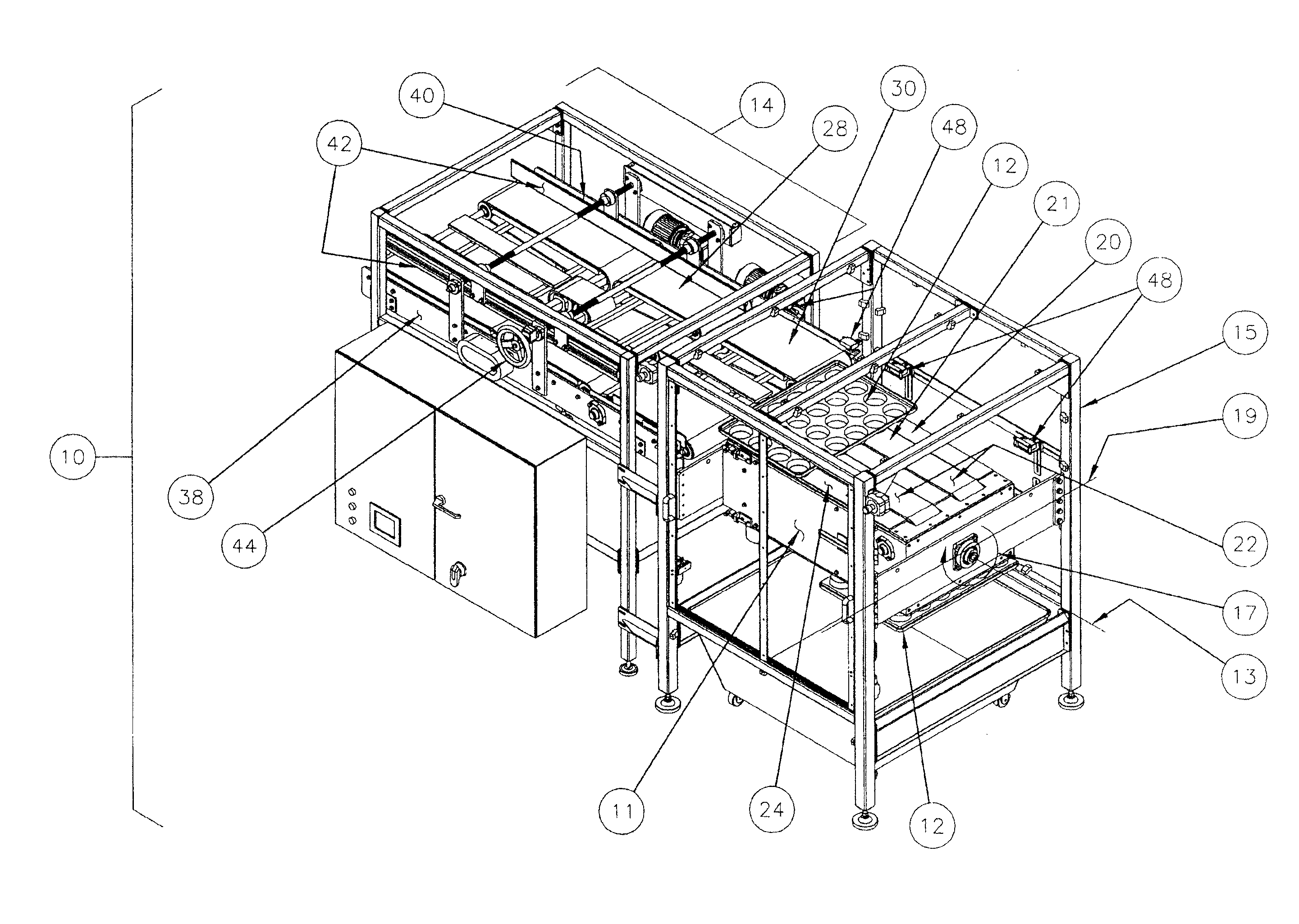
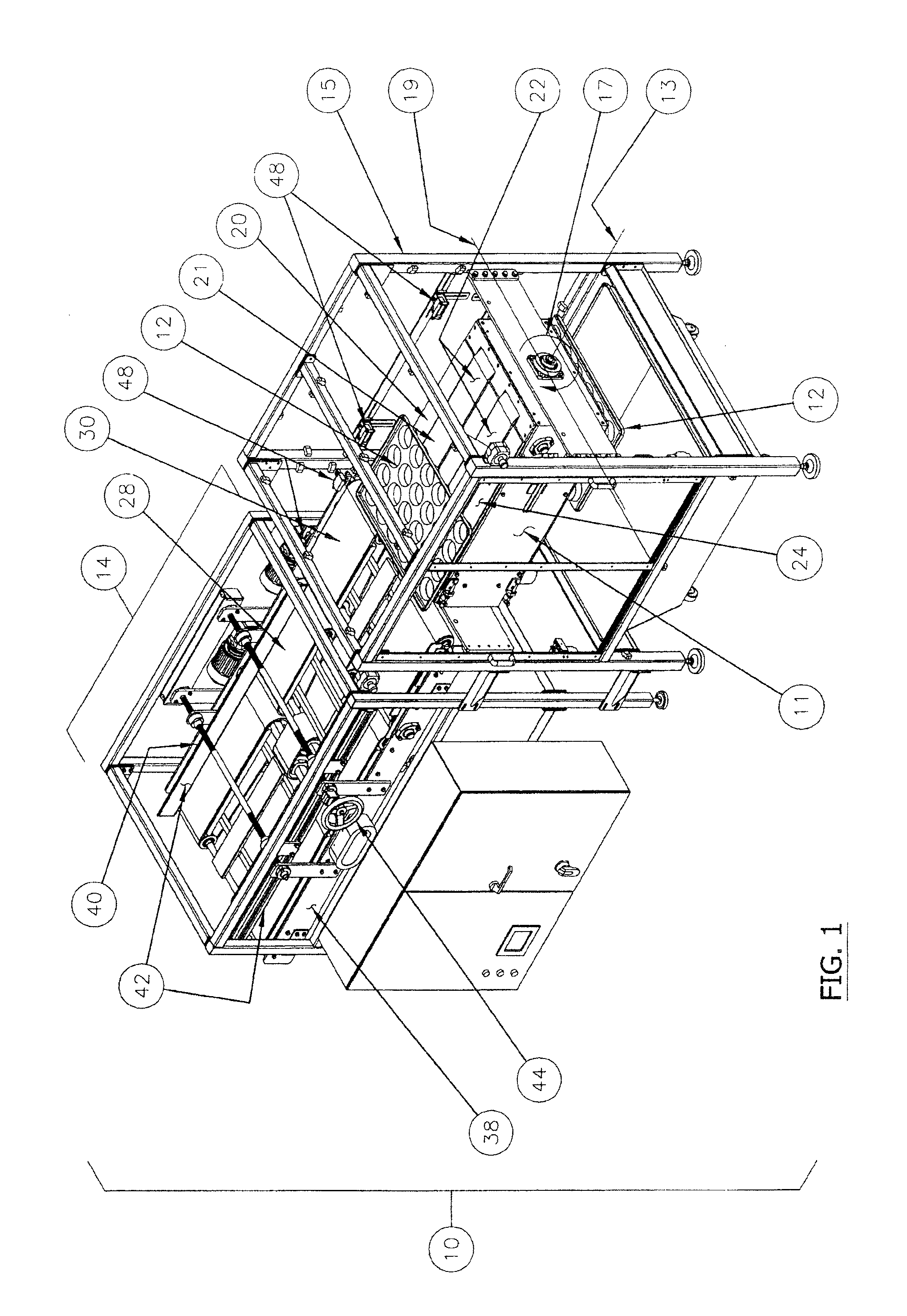
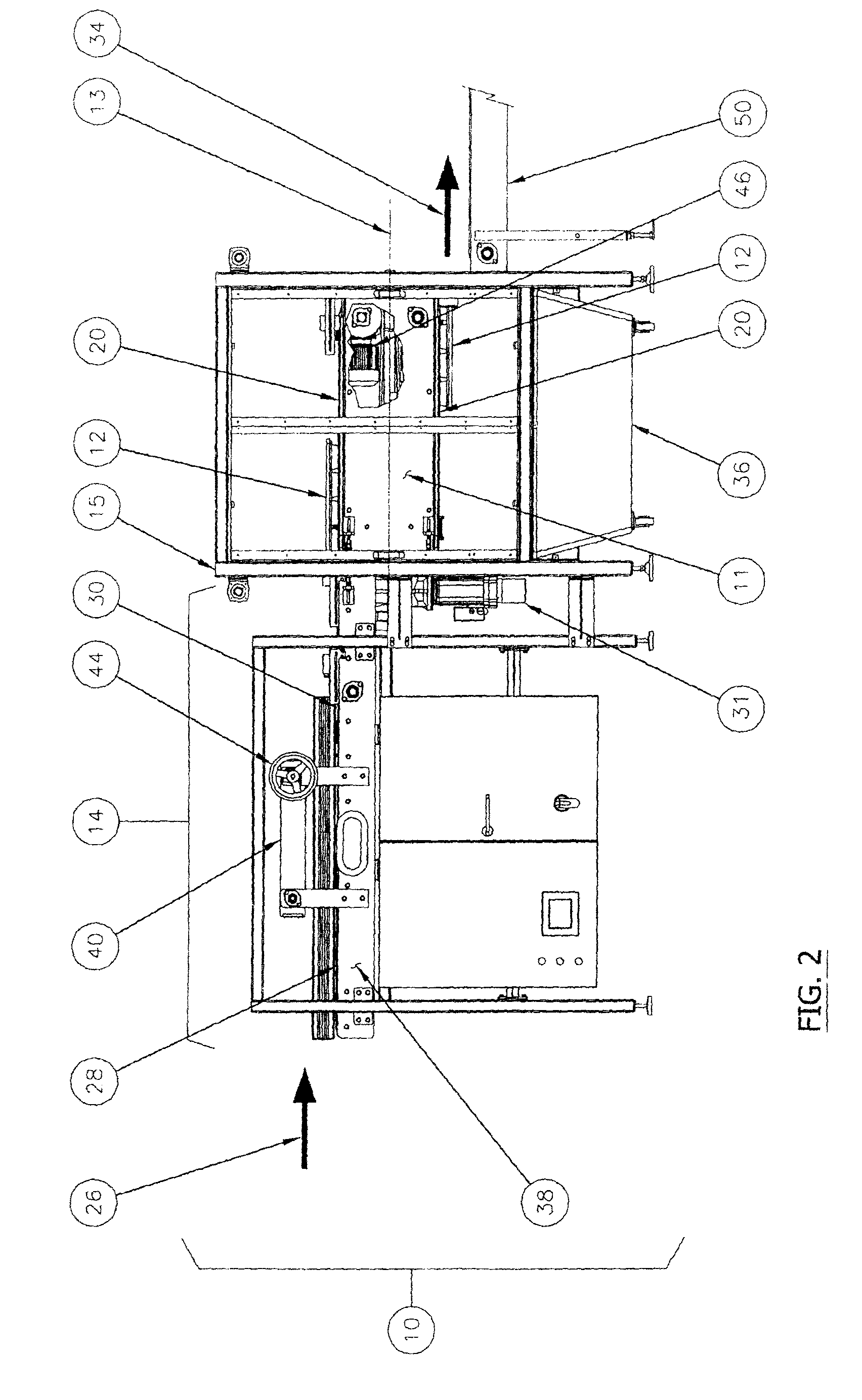
[0020]As noted above, it is desirable to be able to rapidly and reliably invert pans used in a high throughput commercial production setting for a number of reasons, including, but not limited to, emptying goods from the pan, to facilitate cleaning of the pans and to facilitate storage of the pans. It is to be noted that the term “inverted” as used herein is intended to comprise both turning pans upside down which are initially right-side up, and / or vice versa. The process of inverting pans using the pan inverting system of the present invention is more efficient, rapid and reliable than with most prior art pan inverting devices, permitting continuous use at a high-volume throughput rate. Such high-volume throughput rate may be, for example, of the order of 30 or more pans / minute, and more preferably of more than 40 pans / minute. Therefore, the table of the system is able to rotate (i.e. in 180 degree increments) more than 30 times per minute, and more preferably more than 40 times p...


PUM


Abstract

A pan inverting system (10) comprises a rotating table (11) having a central longitudinal axis (13), the table being rotatably mounted within a static frame (15) for rotation about the longitudinal axis (13). Conveyors (21) are disposed on opposed pan-receiving surfaces (20) of the table (11). The conveyors (21) are independently operable to displace a pan (12) along the table (11) in a direction substantially parallel to the longitudinal axis (13). A pan engagement device (24) within the table (11) is operable to releasably fasten the pan (12) to the pan receiving surface (20) of the table (11), such that when the pan (12) is fastened to one of the pan receiving surfaces (20) by the pan engagement mechanism (24), rotation of the table (11) about the longitudinally extending axis (13) will invert the pan (12). The table (11) may also equipped with air headers (507), nozzles and / or air knives (508) to clean the pans (12), for example during the rotating operation, by injecting cleaning air jets onto the surfaces of the pan (12).

Description

CROSS-REFERENCE TO RELATED APPLICATIONS[0001]The present application is a continuation of International Patent Application No. PCT / CA2008 / 001202 filed Jun. 20, 2008, which claims priority on U.S. Provisional Patent Application No. 60 / 945,476 filed Jun. 21, 2007, the entire contents of which are incorporated herein by reference.TECHNICAL FIELD[0002]The present invention relates generally to equipment and systems for the commercial production of food, beverage and / or pharmaceutical goods, and more particularly to pan inverting systems used in such commercial processes.BACKGROUND OF THE ART[0003]In commercial bakeries and other commercial production lines, automated systems and processes are used to produce products, such as breads, rolls, buns, cookies, chocolates, frozen foods, dairy products, beverages, pharmaceuticals and the like, in large volumes and typically in a generally continuous manner. The pans within which such products are contained during the production process are usu...

Claims


Application Information

Patent Timeline
Patent Type & Authority Patents(United States)
IPC IPC(8): B65G47/22
CPCA21B3/16A47L15/0092B08B1/02B08B1/04B08B5/023
Inventor DEPOT, NICOLGENDRON, LUC
Owner REXFAB
Why Eureka
Try Eureka