Press fit passive component

a passive component and plate technology, applied in the field of printed circuit boards, to achieve the effect of less spa

Inactive Publication Date: 2011-11-22
SANGOMA US INC
View PDF27 Cites 23 Cited by
  • Summary
  • Abstract
  • Description
  • Claims
  • Application Information

AI Technical Summary

Problems solved by technology

Conventional surface mount and buried passive components present several disadvantages to circuit board designers.

Method used


Image

  • Press fit passive component
  • Press fit passive component
  • Press fit passive component

Examples


Embodiment Construction

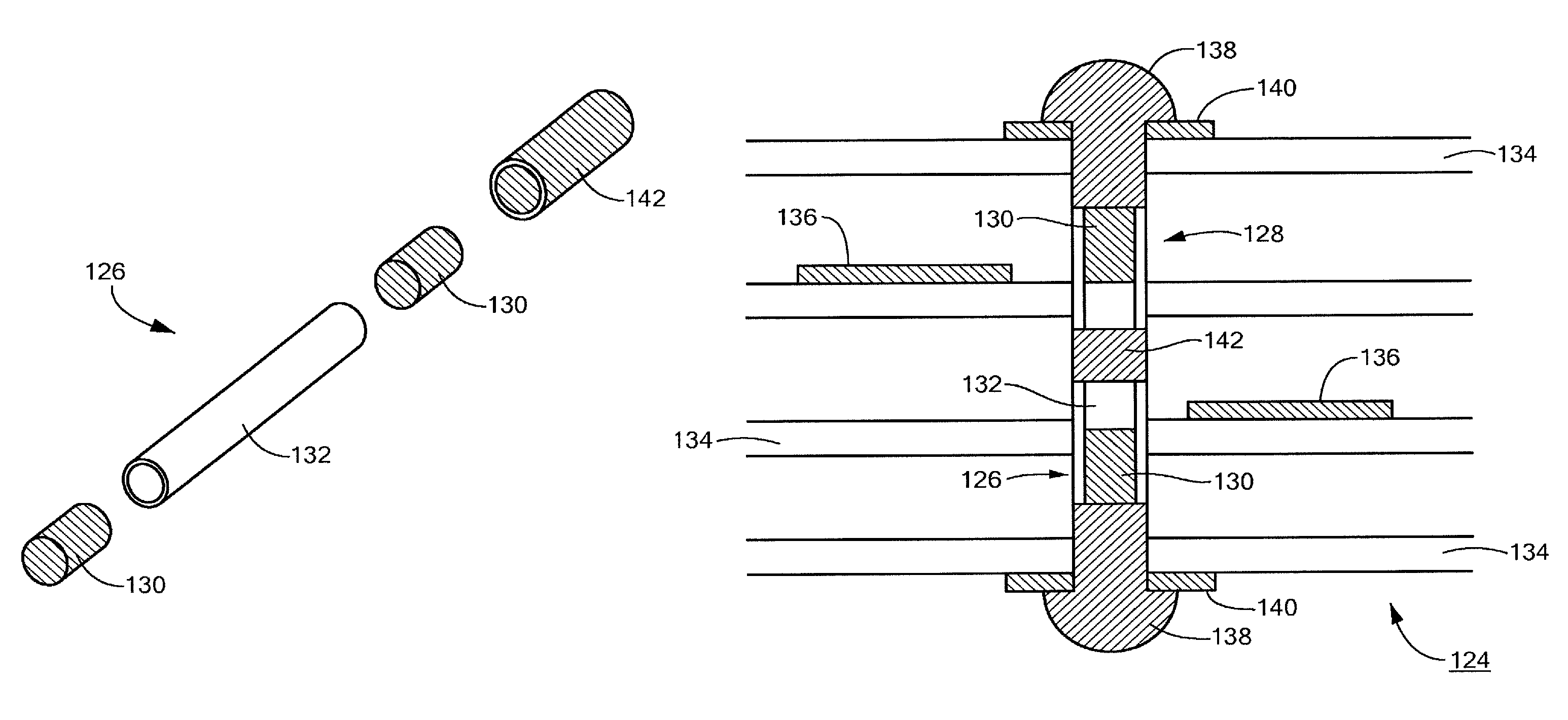
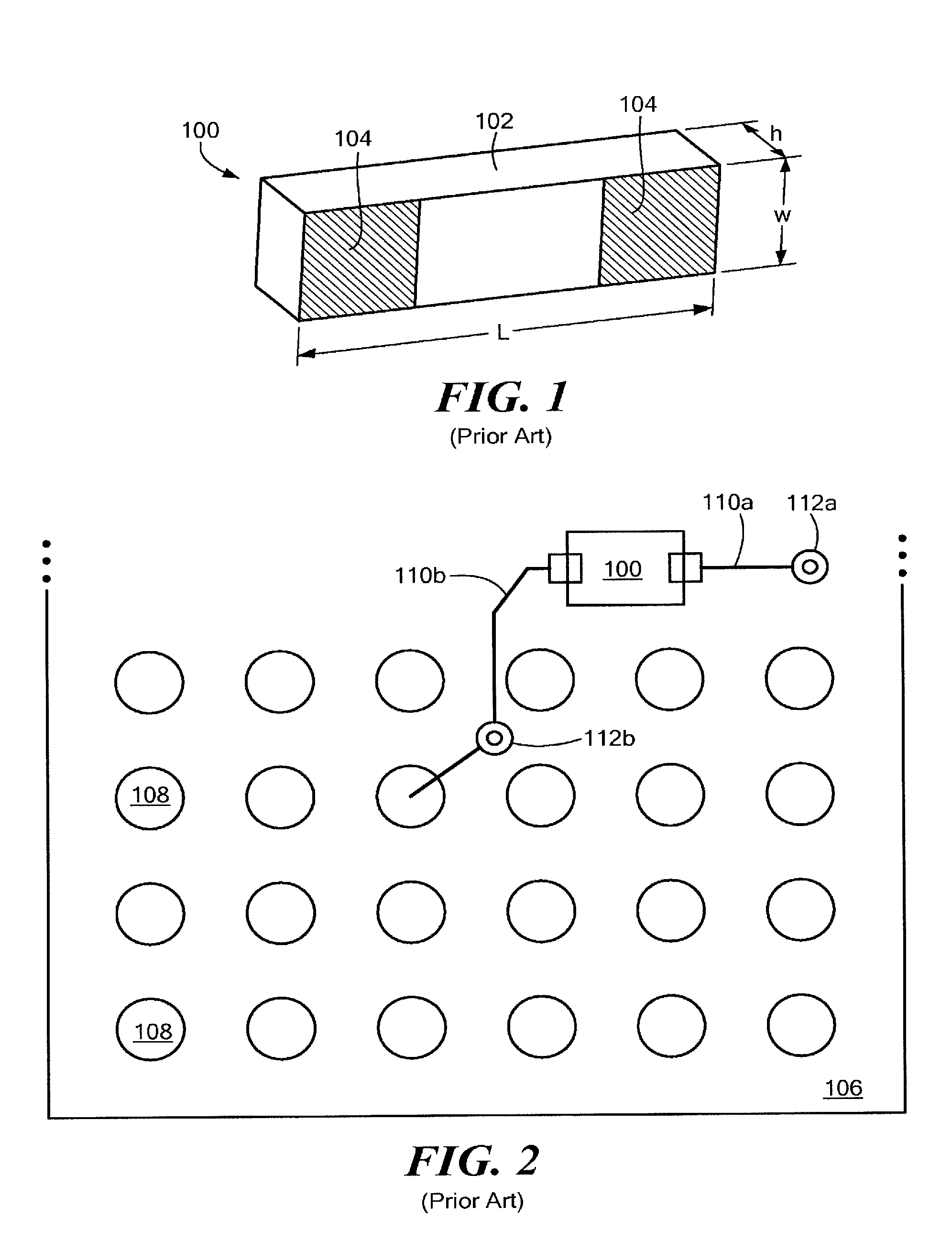
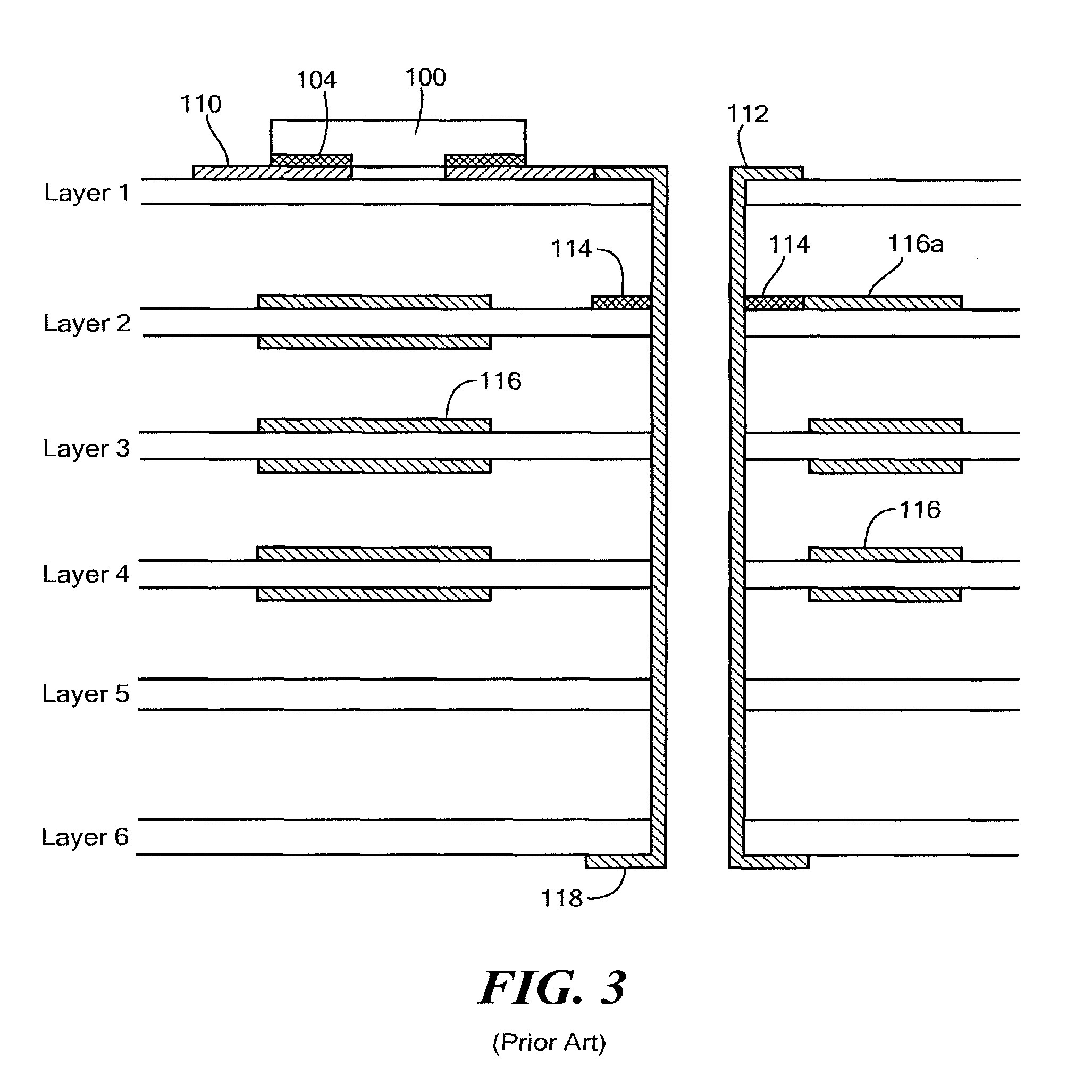
[0030]It has been found that for several types of electronic devices, for example, some telecommunications devices, there is a need to terminate signal traces on the printed circuit board (pcb) with a series resistor in order to match impedance of a signal source (e.g., a driver pin) to the pcb transmission line. However, due to component spacing constraints and limited space on the circuit board for placing resistors, adding even one resistor to a printed circuit board design becomes difficult. Particularly, buried resistors may use up too much valuable horizontal surface area and via space, and the use of conventional surface mount resistors may degrade electrical performance of the device due to extra stub lengths created by the vias, as discussed above. Accordingly, to address these and other problems with conventional passive components, embodiments are directed to press fit passive components that may be located within (or at least partially within) vias on a printed circuit b...


PUM

PropertyMeasurementUnit
widthaaaaaaaaaa
widthaaaaaaaaaa
heightaaaaaaaaaa

Abstract

A press fit passive component, such as a resistor or capacitor, adapted to fit within, or partially within, a via of a printed circuit board. In one example, the press fit passive component has a cylindrically shaped body with solderable terminals at either end of the body, and a dielectric collar disposed at least partially about the cylindrically shaped body.

Description

BACKGROUND[0001]1. Field of Invention[0002]The present invention relates generally to printed circuit boards and electronic components used thereon and, more particularly, to passive electronic components and printed circuit boards including passive components.[0003]2. Discussion of Related Art[0004]Passive components, such as resistors, capacitors and inductors, are commonly provided on printed circuit boards as surface mount (SMT) components. Referring to FIG. 1, there is illustrated one example of a standard surface mount resistor 100. The resistor 100 has a package body 102 with two solderable pads 104 for connecting the resistor to a printed circuit board. Surface mount passive components are generally fairly small. For example, a standard surface mount resistor, such as that illustrated in FIG. 1, may be approximately rectangular with a length, L, of about 0.040 inches (±0.002 inches), a height, h, of about 0.018 inches (±0.002 inches), and a width, w, of about 0.020 inches (±...

Claims


Application Information

Patent Timeline
Patent Type & Authority Patents(United States)
IPC IPC(8): H05K1/18H05K1/11
CPCH05K1/184H05K3/3442H05K3/4046Y02P70/611H05K2201/1059H05K2201/10636Y10T29/49139H05K2201/10583Y02P70/50
Inventor FRASCO, GARY D
Owner SANGOMA US INC
Why Eureka
Try Eureka