Fuser life extension

a technology of fusing parts and life extension, which is applied in the field of electrophotographic devices, can solve the problems of poor adhesion of toner to the substrate, damage to the image known as image mottle, and toner to stick to the fusing member, and achieve the effect of prolonging the operating life of the fuser assembly

Active Publication Date: 2011-11-22
LEXMARK INT INC
View PDF10 Cites 3 Cited by
  • Summary
  • Abstract
  • Description
  • Claims
  • Application Information

AI Technical Summary

Benefits of technology

Performing a temperature compensation if the substrate count corresponds to the predetermined count threshold may comprise adjusting the temperature setpoint value to a compensated temperature setpoint value and adjusting the fusing temperature to correspond with the compensated temperature setpoint value. The compensated temperature setpoint value may be configured to extend the operating life of the fuser assembly.
The temperature compensation may adjust the temperature setpoint value to a compensated temperature setpoint value and may adjust the fusing temperature to correspond to the compensated temperature setpoint value. The compensated temperature setpoint value may be configured to extend the operating life of the fuser assembly.

Problems solved by technology

Poor fusegrade, resulting in poor adhesion of the toner to the substrate, may be caused by insufficient temperature, pressure or time in the nip area.
Moreover, excessive temperature, pressure or time in the nip area may cause damage to the toner image known as image mottle.
Excessive temperature, pressure or time in the nip area may also cause the toner to stick to the fusing members rather than the substrate.

Method used


Image

  • Fuser life extension
  • Fuser life extension
  • Fuser life extension

Examples


Embodiment Construction

In the following detailed description of the preferred embodiments, reference is made to the accompanying drawings that form a part hereof, and in which is shown by way of illustration, and not by way of limitation, specific preferred embodiments in which the invention may be practiced. It is to be understood that other embodiments may be utilized and that changes may be made without departing from the spirit and scope of the present invention.

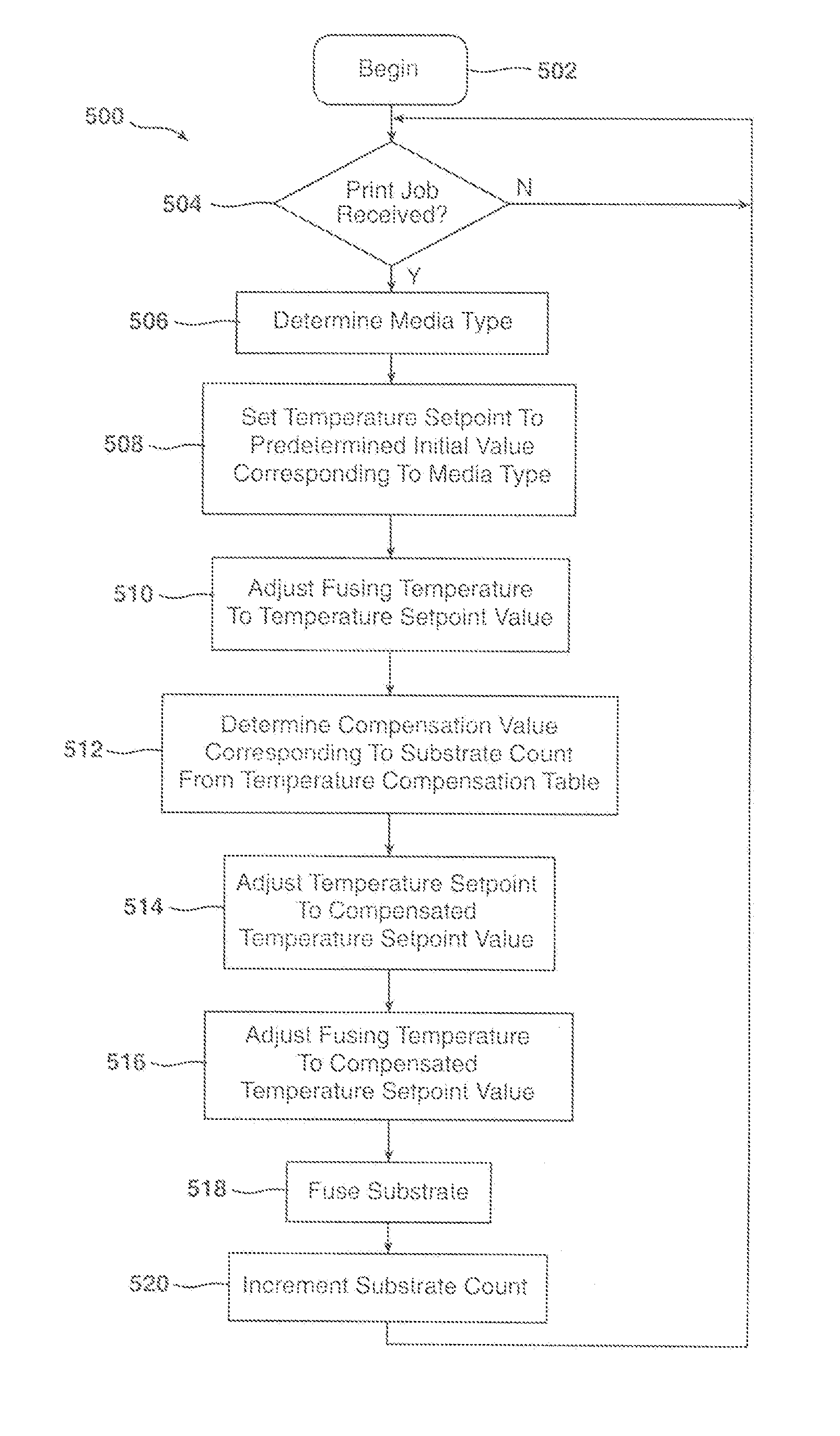
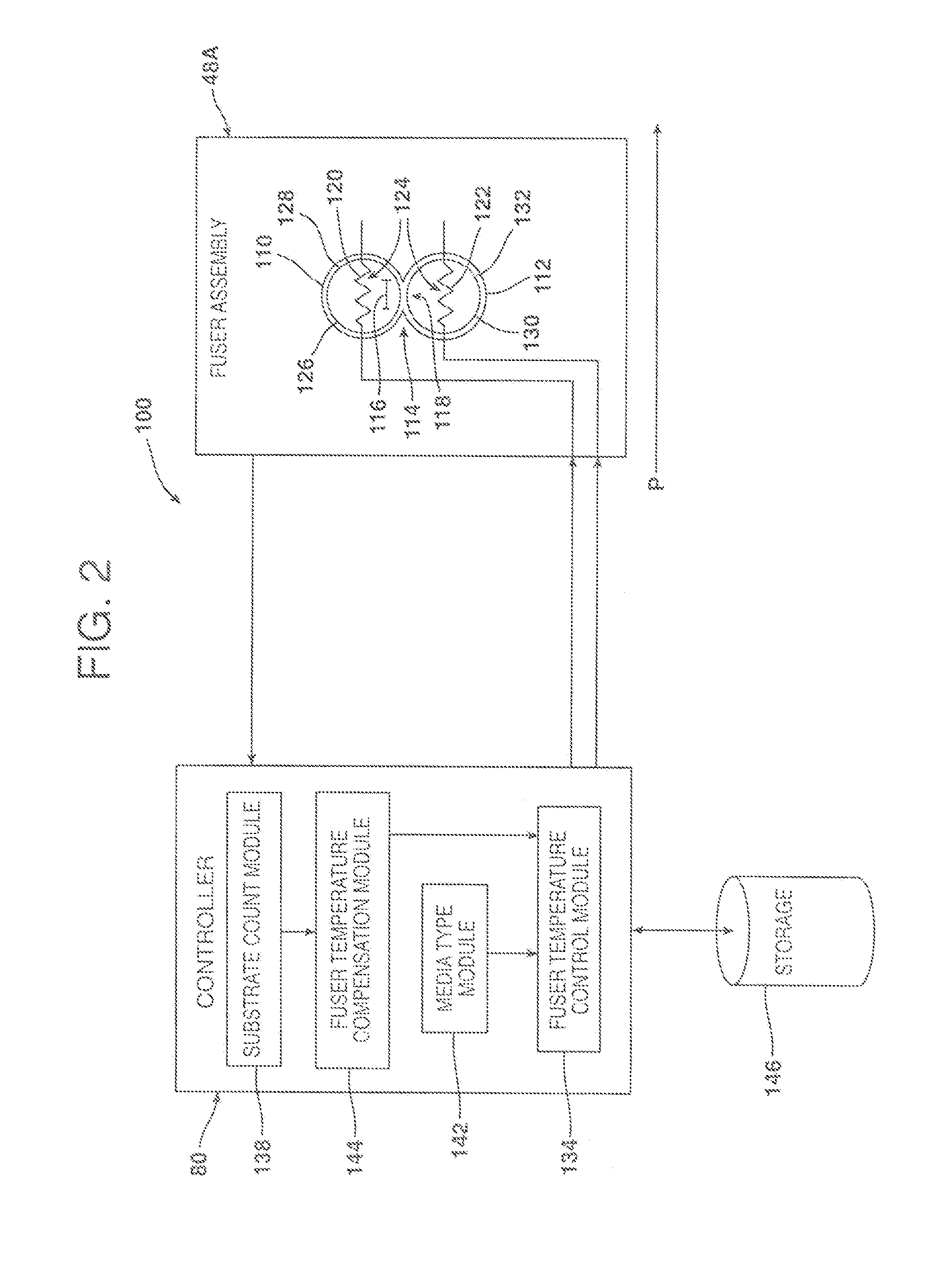
According to an aspect of the present invention, an operating lifetime of a fuser assembly for use in an electrophotographic imaging apparatus may be extended by counting a number of fusing operations performed by the fuser assembly and adjusting a fusing temperature when a predetermined number of fusing operations have been performed. The fusing temperature may be adjusted to a higher temperature or to a lower temperature and the adjustment may be made at one or more predetermined counting events during the lifetime of the fuser assembly. Mor...


PUM


Abstract

A method for extending the operating life of a fuser used in an electrophotographic imaging apparatus is disclosed. A control algorithm monitors the number of substrates processed over the lifetime of the fuser and adjusts the fusing temperature of the fuser to compensate for changes occurring in the nip forming members of the fuser. The useful lifetime of the fuser is extended while fusing quality is maintained. A corresponding fuser assembly is also disclosed.

Description

FIELD OF THE INVENTIONThe present invention relates generally to electrophotographic devices and, more specifically, to techniques for extending fuser life.BACKGROUND OF THE INVENTIONIn electrophotography, an imaging system forms a latent image by exposing select portions of an electrostatically charged photoconductive surface to laser light. Essentially, the density of the electrostatic charge on the photoconductive surface is altered in areas exposed to a laser beam relative to those areas unexposed to the laser beam. The latent electrostatic image thus created is developed into a visible image by exposing the photoconductive surface to toner, which contains pigment components and thermoplastic components. When so exposed, the toner is attracted to the photoconductive surface in a manner that corresponds to the electrostatic density altered by the laser beam. The toner pattern is subsequently transferred from the photoconductive surface to the surface of a print substrate, such as...

Claims


Application Information

Patent Timeline
Patent Type & Authority Patents(United States)
IPC IPC(8): G03G15/20
CPCG03G15/2039
Inventor BLAIR, BRYAN MICHAELLOKOVICH, JAMES ALLENREAM, GREGORY LAWRENCE
Owner LEXMARK INT INC
Why Eureka
Try Eureka