Keyed crown orientation for multi-axial screws

a multi-axial screw and keyed crown technology, applied in the direction of ligaments, prostheses, osteosynthesis devices, etc., can solve the problems of difficult and tedious alignment of these components within the confines of a surgical opening

Active Publication Date: 2011-11-29
WARSAW ORTHOPEDIC INC
View PDF29 Cites 71 Cited by
  • Summary
  • Abstract
  • Description
  • Claims
  • Application Information

AI Technical Summary

Benefits of technology

[0009]In yet another exemplary aspect, the present disclosure is directed to a coupling assembly including an anchor member and a receiver member. The receiver member may have an anchor member end that cooperates with the anchor member and an implant receiving aperture for receiving an implant. The receiver member may include an inner surface and a first rotation-limiting feature associated with the inner surface. A seat member may be disposable within the receiver member between the anchor member and the implant receiving aperture. The seat member may include an outer surface and a second rotation-limiting feature associated with the outer surface. One of the first and second rotation limiting features may include a plurality of positions shaped to cooperate with the other of the first and second rotation limiting features in a manner that permits selective engagement of one of the plurality of positions with the other of the first and second rotation limiting features to limit rotation of the seat member relative to the receiver member.

Problems solved by technology

Alignment of these components can be difficult and tedious within the confines of a surgical opening.

Method used


Image

  • Keyed crown orientation for multi-axial screws
  • Keyed crown orientation for multi-axial screws
  • Keyed crown orientation for multi-axial screws

Examples


Embodiment Construction

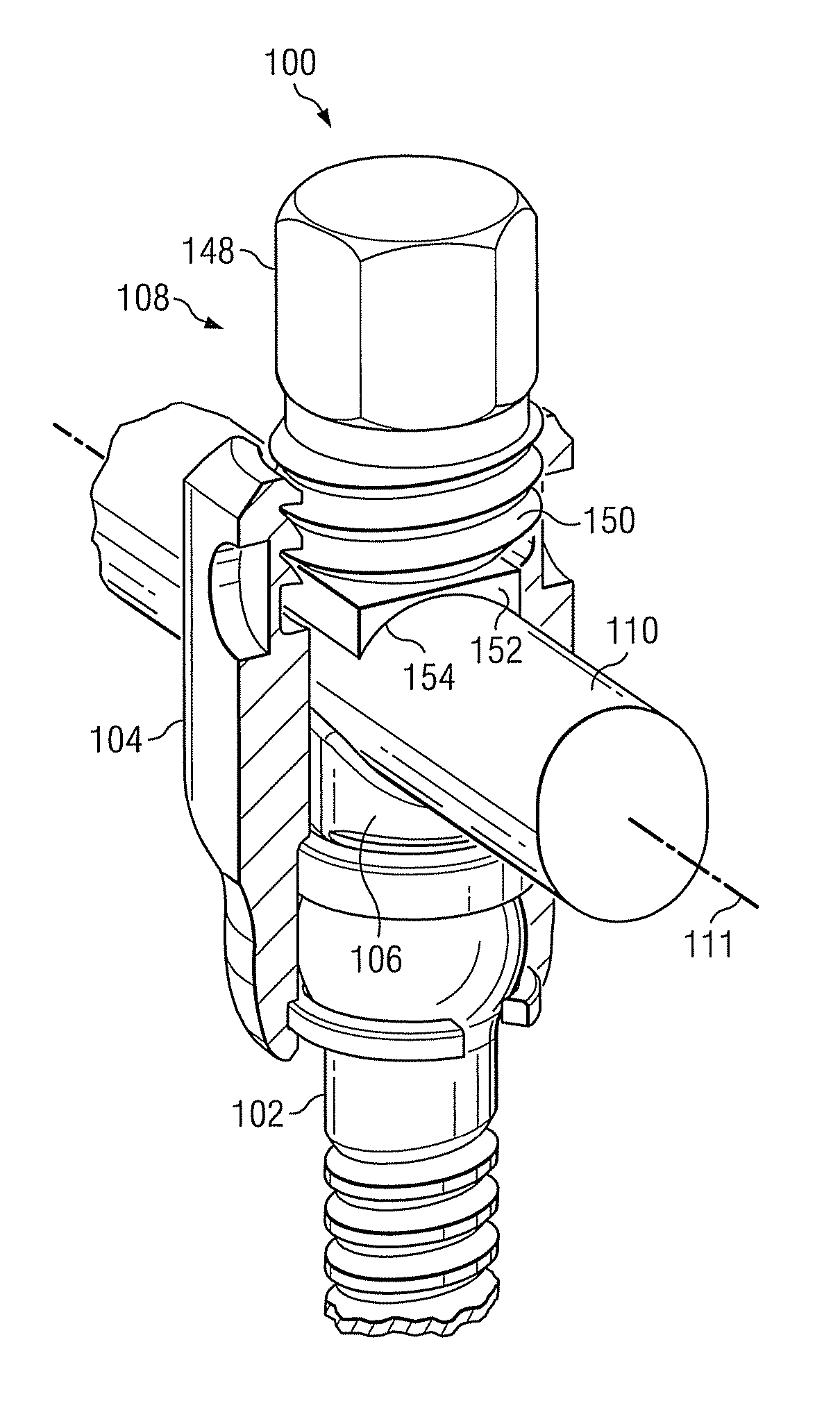
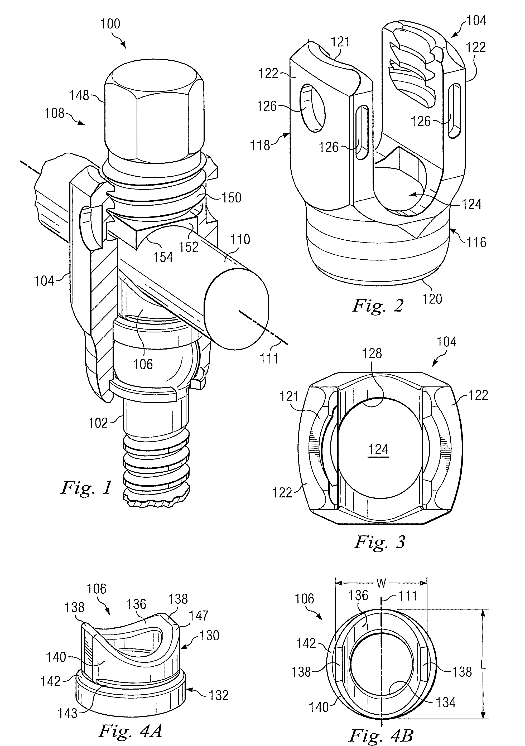
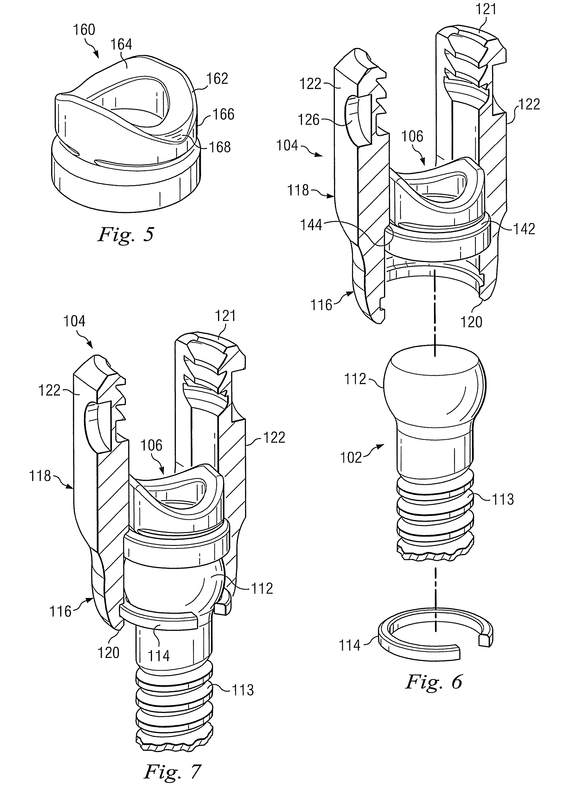
[0036]The present invention relates generally to coupling assemblies for anchoring systems used for implantation of a vertebral device. For the purposes of promoting an understanding of the principles of the invention, reference will now be made to embodiments or examples illustrated in the drawings and specific language will be used to describe the same. It will nevertheless be understood that no limitation of the scope of the invention is thereby intended. Any alterations and further modifications in the described embodiments, and any further applications of the principles of the invention as described herein are contemplated as would normally occur to one skilled in the art to which the invention relates.

[0037]Coupling assemblies typically include an anchor member for engaging the coupling assembly to an underlying bony structure, a receiver member for receiving the implant, and a securing member for securing the implant to the receiver member. The exemplary coupling assemblies d...


PUM


Abstract

A coupling assembly may include an anchor member, a receiver member, and a seat member. The receiver member may have an anchor member end that cooperates with the anchor member and may have an implant receiving aperture for receiving an implant. The seat member may be disposable within the receiver member between the anchor member and the implant receiving aperture. First and second rotation-limiting features may be engageable to limit rotation of the seat member relative to the receiver member.

Description

BACKGROUND[0001]The present disclosure generally relates to orthopedic coupling assemblies for anchors used with implants for correction of spinal injuries or deformities.[0002]In the realm of orthopedic surgery, implant systems may be utilized to fix the position of bones. In this way, the healing of a broken bone can be promoted, and malformations or other injuries can be corrected. Typical implant systems include several pieces. Bone screws, for example, are well know as fixation devices, which are connected or adjoined to a particular bone as a connection between the remainder of the implant and the bone. With rod-type implants, a series of two or more screws are typically inserted into two or more vertebrae to be instrumented. The rod is then placed within or coupled to the heads of the screws, or is placed within a connecting device that links the rod and a screw head, and the connections are tightened. In this way, a rigid supporting structure is fixed to the vertebrae, with ...

Claims


Application Information

Patent Timeline
Patent Type & Authority Patents(United States)
IPC IPC(8): A61B17/70
CPCA61B17/7002A61B17/7037A61B17/7032A61B2019/307A61B2090/037A61B17/70A61B17/86
Inventor JUSTIS, JEFF R.DEWEY, JONATHAN M.
Owner WARSAW ORTHOPEDIC INC
Why Eureka
Try Eureka