Shoulder implant assembly

a shoulder joint and implant technology, applied in shoulder joints, prosthesis, medical science, etc., can solve the problem of not being able to determine well in advance of the procedure whether to perform a traditional shoulder or a reverse shoulder

Active Publication Date: 2011-12-06
BIOMET MFG CORP
View PDF112 Cites 57 Cited by
  • Summary
  • Abstract
  • Description
  • Claims
  • Application Information

AI Technical Summary

Benefits of technology

[0008]Another embodiment of the invention provides an assembly of implant components for a shoulder joint having a humerus and a glenoid. The assembly includes a plurality of humeral stems, a plurality of heads, and a plurality of cups configured to articulate with the heads. The assembly also includes a plurality of glenoid adaptors for a reverse shoulder arthroplasty, and a plurality of humeral adaptors for traditional shoulder arthroplasty. The humeral or glenoid adaptors have an offset feature which allows for relative positioning of the humeral or glenoid articulating surfaces. Each glenoid adaptor is configured to connect one of the heads to the glenoid when one of the cups is connected to one of the humeral stems. Each humeral adaptor is configured to connect one of the heads to one of the humeral stems when one of the cups is connected to the glenoid.

Problems solved by technology

It is not always practical to determine well in advance of the procedure whether a reverse or traditional shoulder prosthesis should be used.

Method used


Image

  • Shoulder implant assembly
  • Shoulder implant assembly
  • Shoulder implant assembly

Examples


Embodiment Construction

[0057]The following description of the preferred embodiments of the invention is merely exemplary in nature and is in no way intended to limit the invention, its application, or uses.

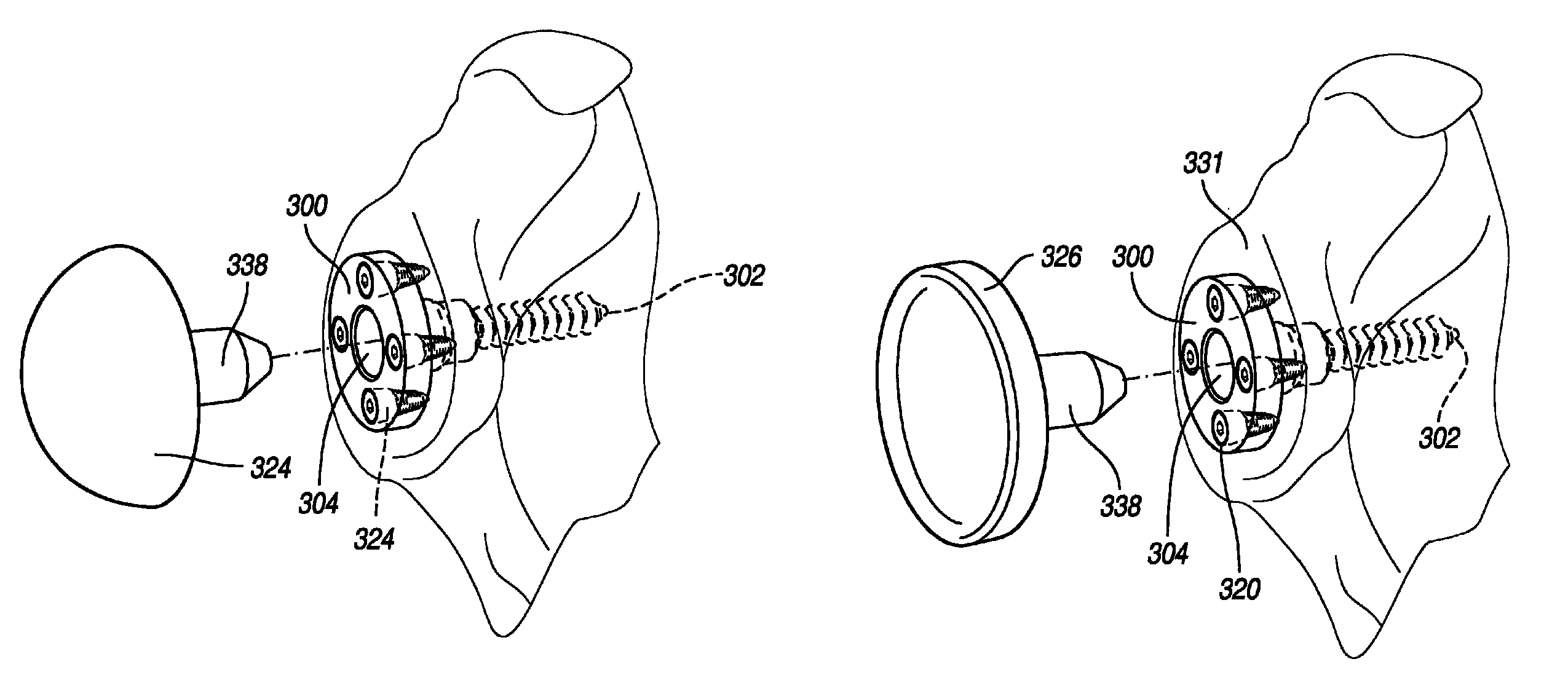
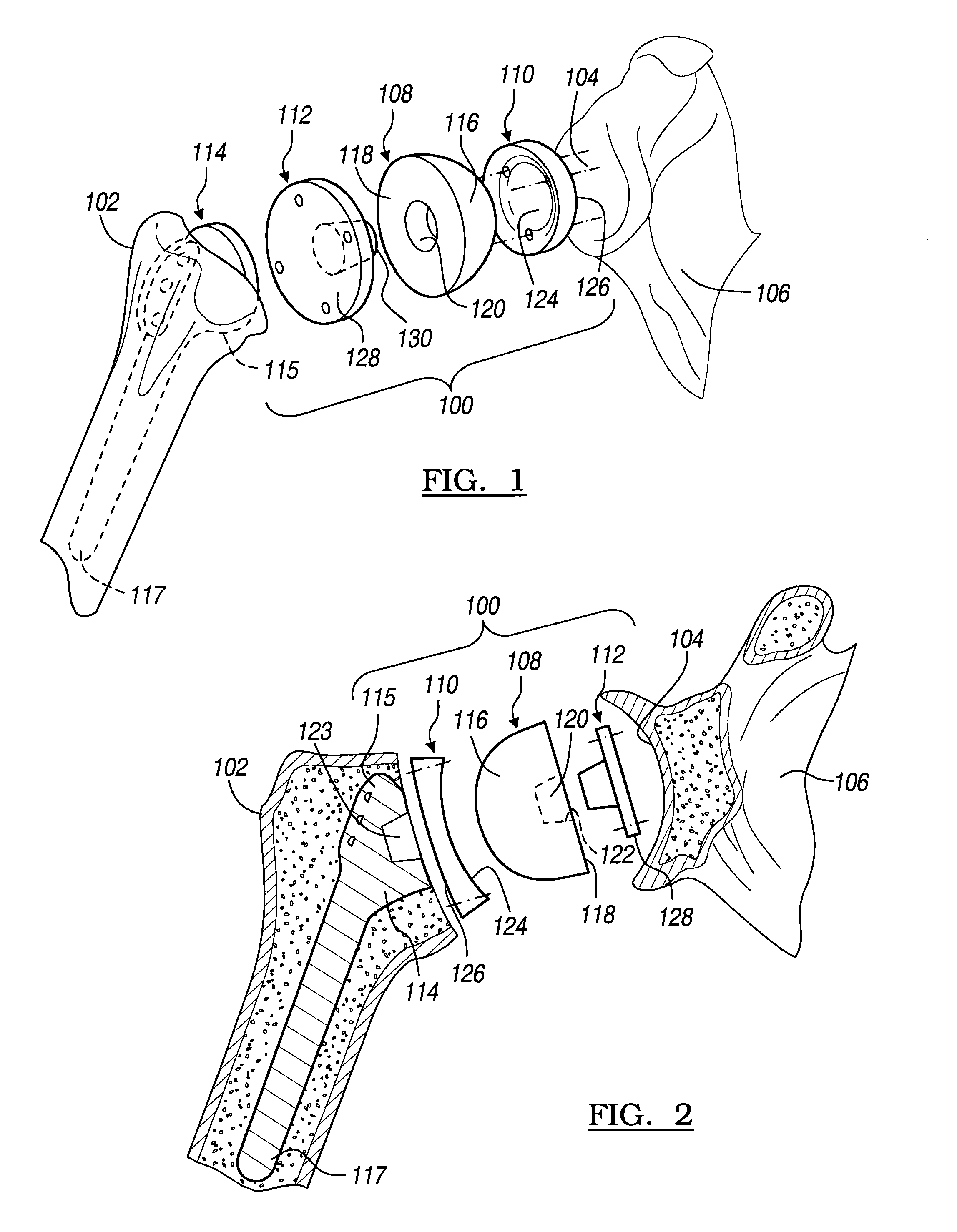
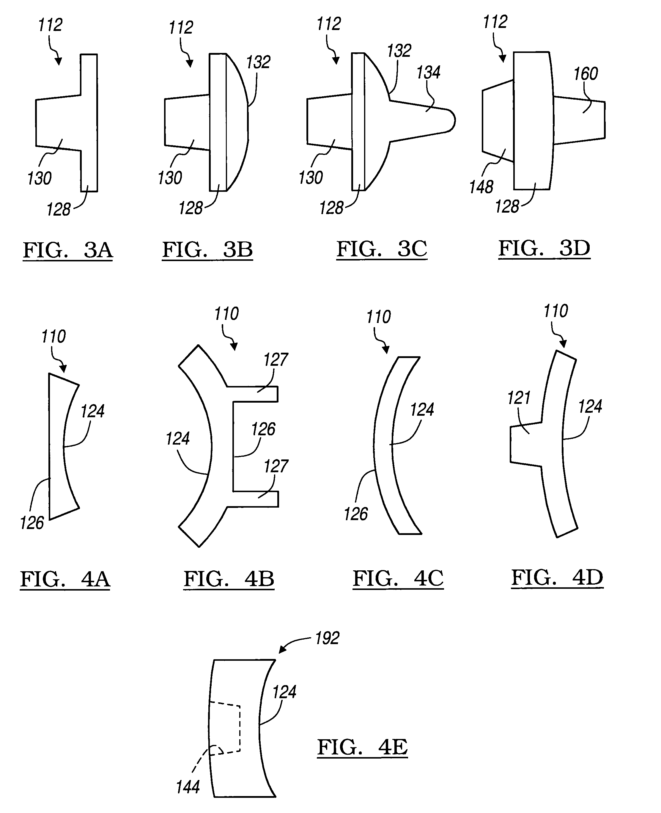
[0058]Referring to FIGS. 1 and 2, there is shown an embodiment of an implant assembly 100 for a total shoulder joint replacement. The implant assembly 100 is configured to be implanted between a resected humerus 102 and a glenoid cavity (“glenoid”) 104 of a scapula 106 in one of two ways, i.e., in a traditional arthroplasty depicted in FIG. 1, or in a reverse arthroplasty depicted in FIG. 2, by selecting and / or reconfiguring appropriately the components of the implant assembly 100. The implant assembly 100 includes a head 108, a cup 110, and an adaptor 112. The implant assembly 100 may also include a humeral stem 114 that has a proximal end 115 and a distal end 117.

[0059]Other embodiments of the implant assembly are shown in FIGS. 5A, 6A, 12, and 13 for traditional shoulder replacement, and in FIGS. 5B,...


PUM


Abstract

An implant assembly and associated method for selectively performing reverse and traditional arthroplasty for a shoulder joint that includes a humerus and a glenoid. The implant assembly may include a head, a cup, a humeral stem and an adaptor. The method includes inserting the humeral stem to the humerus and connecting a male taper of the adaptor to a female taper of the head. For reverse arthroplasty, the method includes attaching the adaptor to the glenoid and the cup to the stem. For traditional arthroplasty, the method includes attaching the adaptor to the humeral stem and the cup to the glenoid. The method also includes articulating the head with the cup.

Description

CROSS-REFERENCE TO RELATED APPLICATIONS[0001]This application is a continuation-in-part application of U.S. patent application Ser. No. 11 / 234,743 filed on Sep. 23, 2005, which is a continuation-in-part of U.S. patent application Ser. No. 10 / 680,924 filed on Oct. 8, 2003 and issued Feb. 13, 2007 as U.S. Pat. No. 7,175,663. The disclosure of the above applications is incorporated herein by reference.FIELD OF THE INVENTION[0002]The present invention relates to an implant assembly for shoulder joint replacement.BACKGROUND OF THE INVENTION[0003]A natural shoulder joint may undergo degenerative changes caused by a variety of reasons. When these degenerative changes become so far advanced and irreversible, it may ultimately become necessary to replace a natural shoulder joint with a prosthetic shoulder joint. In the traditional implantation of a shoulder joint prosthesis, the natural head portion of the humerus is resected and a cavity is created in the intramedullary canal of the host hu...

Claims


Application Information

Patent Timeline
Patent Type & Authority Patents(United States)
IPC IPC(8): A61F2/40
CPCA61F2/40A61B17/86A61F2/30767A61F2/4014A61F2/4059A61F2/4081A61F2002/30331A61F2002/30332A61F2002/305A61F2002/30537A61F2002/30538A61F2002/30604A61F2002/30607A61F2002/30616A61F2002/30736A61F2002/3085A61F2002/30878A61F2002/30879A61F2002/30884A61F2002/30901A61F2002/4011A61F2002/4018A61F2002/4022A61F2002/4029A61F2002/4033A61F2002/4037A61F2002/4044A61F2002/4051A61F2002/4062A61F2002/4066A61F2002/407A61F2002/4074A61F2002/4077A61F2002/4085A61F2220/0025A61F2220/0033A61F2250/0004A61F2250/0006A61F2250/0062A61F2310/00029
Inventor WINSLOW, NATHAN A.BERELSMAN, BRIAN K.ISCH, BRYCE A.MCDANIEL, JOHN M.KATRANA, NICHOLAS J.
Owner BIOMET MFG CORP
Why Eureka
Try Eureka