Antenna test system

a test system and antenna technology, applied in the direction of transmission monitoring, electromagnetic wave modulation, instruments, etc., can solve the problems of significant practical limitations, susceptibility to effects, and measurement techniques known as far-field testing, and achieve the effect of quick and accurate measurement of the far-field pattern(s)

Active Publication Date: 2011-12-13
THE UNITED STATES OF AMERICA AS REPRESENTED BY THE SECRETARY OF THE NAVY
View PDF23 Cites 12 Cited by
  • Summary
  • Abstract
  • Description
  • Claims
  • Application Information

AI Technical Summary

Benefits of technology

[0010]A method and system are provided for testing of antenna systems, features and equipment using position determination, orientation determination, and test pattern analysis between an RF probe and antenna(s) under test at a variety points to quickly and accurately measure the far-field pattern(s).

Problems solved by technology

One problem in the development and manufacture of antennas is the accurate measurement of antenna performance.
This measurement technique, known as far-field testing, suffers from significant practical limitations, such as susceptibility to the effects of weather, ground reflections, and increasing real estate costs.
Moreover, there are significant logistical limitations.
Relative movement (e.g. vibration) between the probe and an AUT may introduce inaccuracies / errors into the process.
This form of testing is cumbersome and expensive.
Depending on the location of the antenna to be tested, the cost of its transportation to and from the test facility, and the opportunity cost while the antenna is out of service, the indoor testing process is not always a cost-effective means of evaluating an antenna.
The vehicle is not in its normal environment (over real ground), and the turntable itself can introduce error.
Moreover, these large test ranges and turntables are plainly an expensive infrastructure.
However, traditional GPS systems used in connection with antenna test systems per se do not provide sufficient information to provide adequate testing results.

Method used


Image

  • Antenna test system
  • Antenna test system
  • Antenna test system

Examples


Embodiment Construction

[0022]For the purposes of promoting an understanding of the principles of the invention, reference will now be made to the embodiments illustrated in the drawings, which are described below. The embodiments disclosed below are not intended to be exhaustive or limit the invention to the precise form disclosed in the following detailed description. Rather, the embodiments are chosen and described so that others skilled in the art may utilize their teachings. It will be understood that no limitation of the scope of the invention is thereby intended. The invention includes any alterations and further modifications in the illustrated devices and described methods and further applications of the principles of the invention which would normally occur to one skilled in the art to which the invention relates.

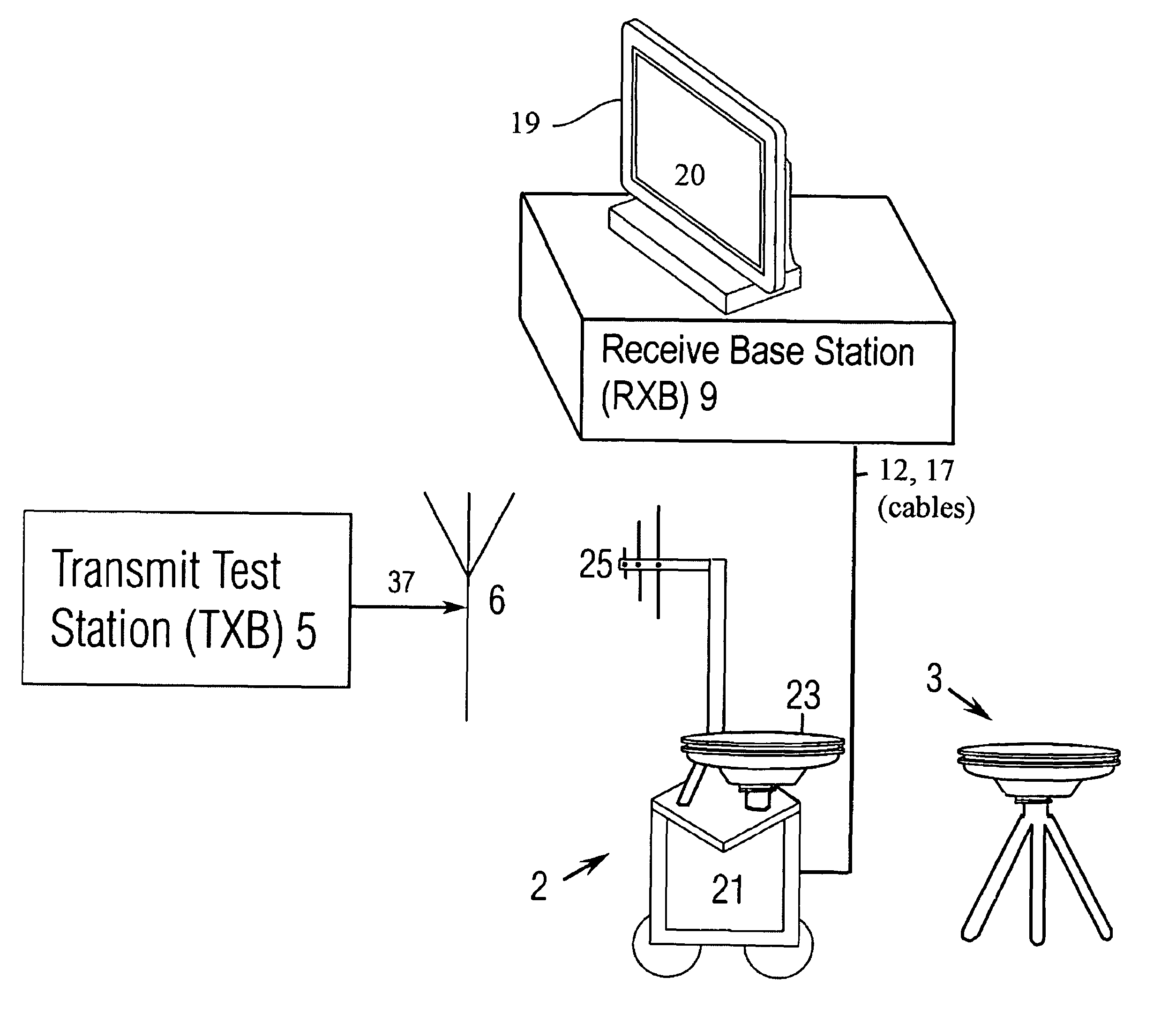
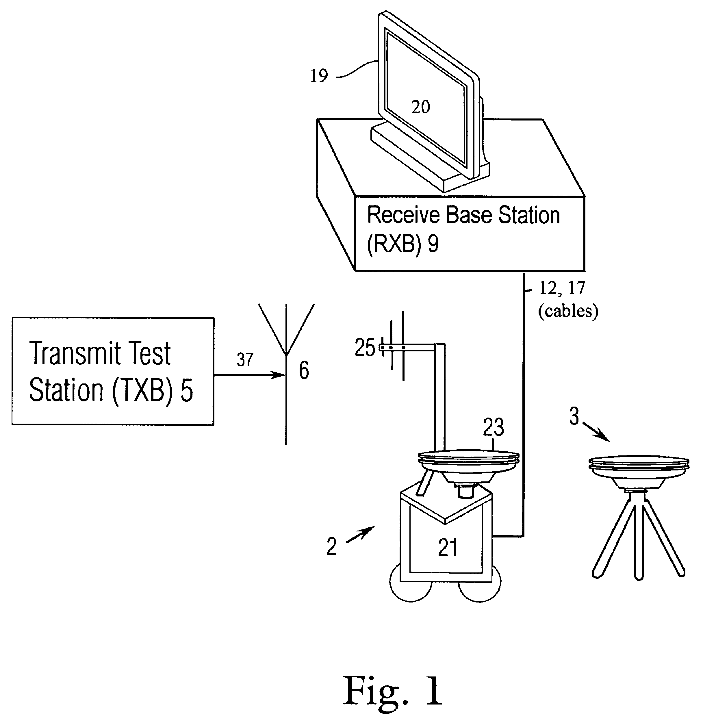
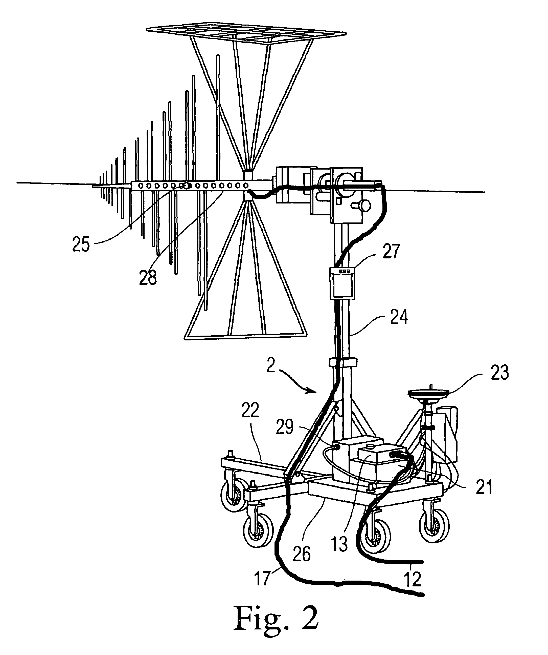
[0023]A method for testing and a highly automated portable “test anywhere” test system for pattern testing of antenna systems is provided. Exemplary ATS, in accordance with the invention...


PUM


Abstract

A method and system are provided for testing antenna systems using position determination, orientation determination, test pattern analysis using a variety of factors and equipment including positions and orientation of antenna(s) under test at specific points and signal processing systems.

Description

STATEMENT REGARDING FEDERALLY SPONSORED RESEARCH OR DEVELOPMENT[0001]The invention described herein was made in the performance of official duties by an employee of the Department of the Navy and may be manufactured, used, licensed by or for the United States Government for any governmental purpose without payment of any royalties thereon.FIELD OF THE INVENTION[0002]A system and method is provided that relates to automated test systems, and more particularly to a highly automated test system for the purposes of pattern testing of antenna systems.BACKGROUND OF THE INVENTION[0003]High performance antennas are becoming increasingly prevalent as spacecraft, aircraft, ship, and ground vehicle mission requirements become more sophisticated. In particular, greater precision in simulation and design of antennas, transmitters and end items antennas and transmitters are mounted upon is needed for a variety of reasons.[0004]One problem in the development and manufacture of antennas is the accu...

Claims


Application Information

Patent Timeline
Patent Type & Authority Patents(United States)
IPC IPC(8): G01R29/10
CPCG01R29/10
Inventor SNOW, JEFFREY M.SCHUMM, MICHAELSHAFF, WILLIAM L.CARLSON, TERRYBAKER, CARL
Owner THE UNITED STATES OF AMERICA AS REPRESENTED BY THE SECRETARY OF THE NAVY
Why Eureka
Try Eureka