
Gauge to measure distortion in glass sheet

a technology of distortion measurement and glass sheet, which is applied in the direction of optically investigating flaws/contamination, instruments, computing, etc., can solve the problems of reducing the throughput of measurements obtained, requiring the use of expensive and fragile precision motion components, etc., and achieves the effect of fast and accurate measurement of distortion and cost effectiv

Inactive Publication Date: 2008-05-22
CORNING INC
View PDF8 Cites 0 Cited by
  • Summary
  • Abstract
  • Description
  • Claims
  • Application Information

AI Technical Summary

Benefits of technology

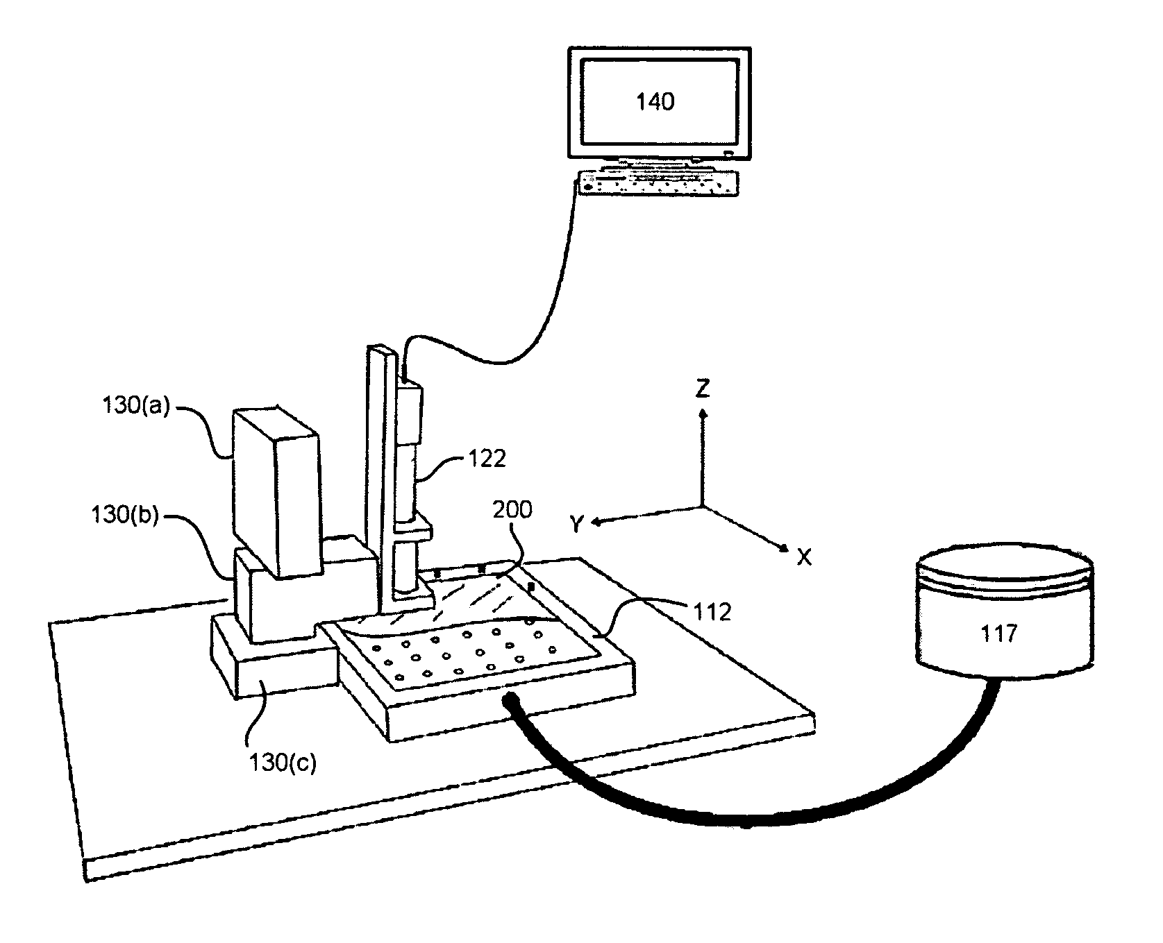
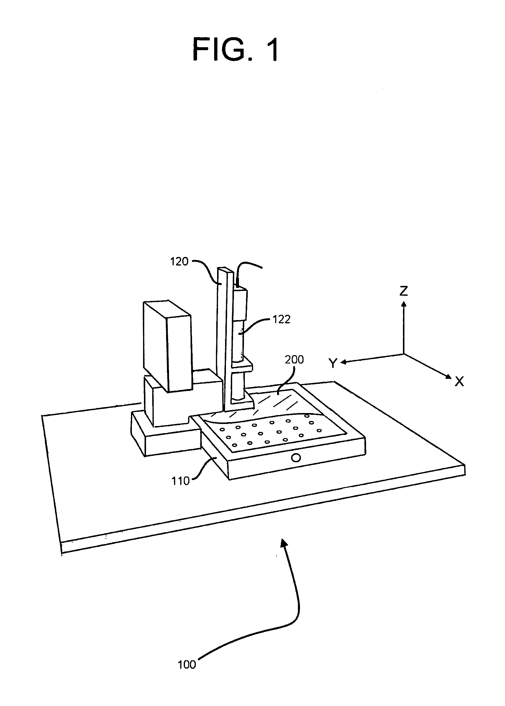
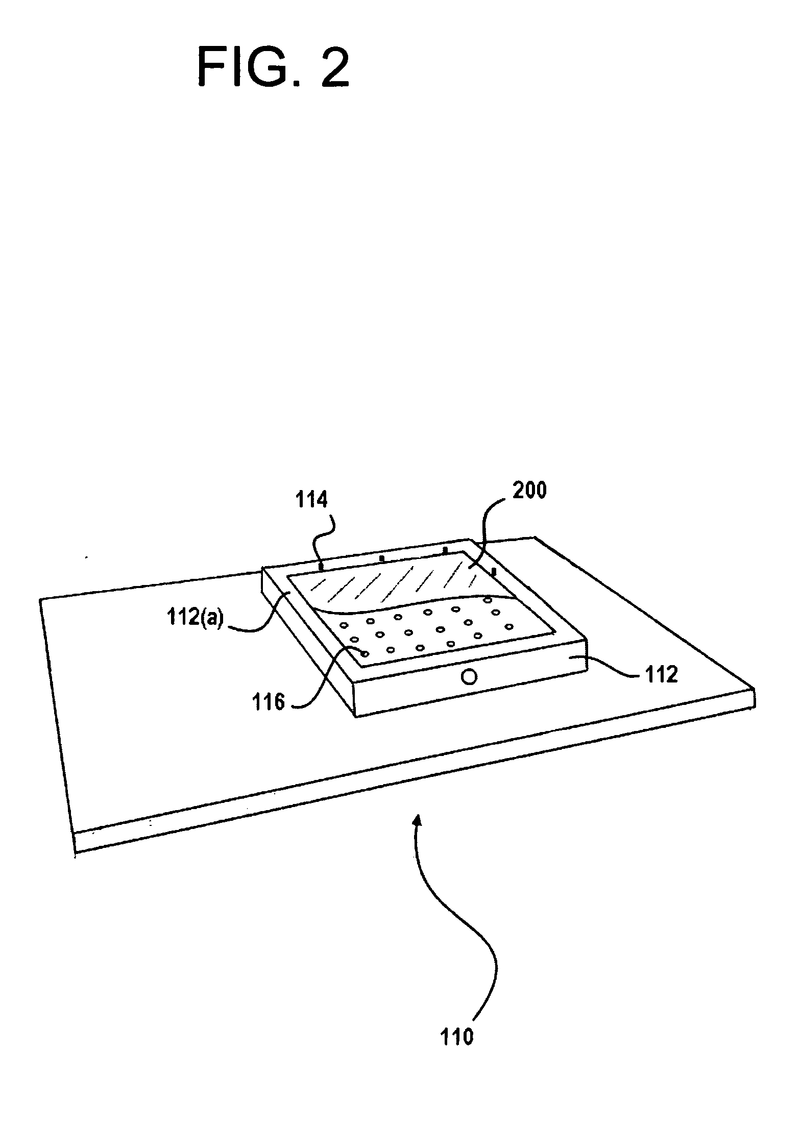
[0006]The present invention provides a cost effective apparatus that can quickly and accurately measure the distortion of a planar substrate, such as a glass sheet, as it undergoes some form of distortion causing treatment, such as stress relaxation as it is cut into smaller pieces or compaction as it is thermally annealed. Generally, the inventive apparatus comprises a plurality of image capturing devices, one for each reference mark on the substrate, and utilizes the plurality of image capturing devices to measure the mark positions both before and after the treatment. The image capturing device positions remain fixed and thus do not move during the course of measurement. As such, mark position changes will be measured directly within the field-of-view (FOV) of each respective image capturing device.
[0007]Since the multiple image capturing device coordinate measuring system of the present invention is not moved nor touched during the course of measurement the system is very stable and robust. Furthermore, the implementation of multiple fixed image capturing devices eliminates the need for expensive precision motion systems previously used to position the image capturing device. Still further, since the multiple image capturing devices themselves provide for a stable reference system, the fragile glass reference plate is also no longer needed.
[0008]Several advantages and benefits can be provided by various aspects of the present invention. First, since the mark positions are determined completely within the cameras' FOV, the need for camera motion, as present in prior technology, can be avoided. Measurements of multiple mark positions can also be made simultaneously with the new system, whereas prior technologies required movement of a single camera from mark to mark, which increases total measurement time. Still further, since there is no need for a high precision motion system or the fragile reference plate, maintenance of the inventive apparatus is relatively lower.

Problems solved by technology

These current single camera CMM's require the use of expensive and fragile precision motion components.
Additionally, the motion of the single camera can reduce the throughput of the measurements obtained.

Method used


Image

  • Gauge to measure distortion in glass sheet
  • Gauge to measure distortion in glass sheet
  • Gauge to measure distortion in glass sheet

Examples


Embodiment Construction

[0019]The following description of the invention is provided as an enabling teaching of the invention in its best, currently known embodiment. To this end, those skilled in the relevant art will recognize and appreciate that many changes can be made to the various embodiments of the invention described herein, while still obtaining the beneficial results of the present invention. It will also be apparent that some of the desired benefits of the present invention can be obtained by selecting some of the features of the present invention without utilizing other features. Accordingly, those who work in the art will recognize that many modifications and adaptations to the present invention are possible and can even be desirable in certain circumstances and are a part of the present invention. Thus, the following description is provided as illustrative of the principles of the present invention and not in limitation thereof.

[0020]As used herein, the singular forms “a,”“an” and “the” incl...


PUM


Abstract

Disclosed is a coordinate measuring apparatus for measuring distortion and or dimensional variations in one or more planar substrates. In one aspect, the coordinate measuring apparatus comprises a base assembly comprising a base plate having a top surface configured to receive the planar substrate; and a multi-dimensional array of image capturing devices, each image capturing device having a field of view and being positioned in a plane parallel to and in overlying registration with at least a portion of the top surface of the base plate. The plurality of image capturing devices are oriented perpendicular to the plane of the multi-dimensional array such that the field of view of each image capturing device can capture at least a portion of the top surface of the base plate. Further, each of the plurality of image capturing devices can be selectively positioned at predetermined coordinates defined within the plane of the multi-dimensional array.

Description

BACKGROUND OF THE INVENTION[0001]1. Field of the Invention[0002]The present invention relates generally to coordinate measuring devices and, more particularly, to an apparatus and method for measuring distortion in a planar substrate.[0003]2. Technical Background[0004]To measure distortion of a glass sheet as it undergoes a distortion causing treatment (e.g. cutting; annealing), the positions of markings on the glass are typically measured both before and after the treatment. The amount of change in positions of these marks as a result of the treatment is defined as the distortion. Current substrate distortion gauges are typically coordinate measurement machines (CMMs) that combine machine vision with precision motion in order to measure positions with high accuracy.[0005]In one current approach, conventional CMM designs utilize precision motion of a single camera together with a stationary glass reference plate on the machine base that is scribed with a grid of marks. Part mark pos...

Claims


Application Information

Patent Timeline
Patent Type & Authority Applications(United States)
IPC IPC(8): G06K9/46
CPCG01B11/306G01B11/245G01B11/30G01N21/88
Inventor SHARPS, ROBERT WENDELL
Owner CORNING INC
Learn More