
Triangular asynchronous replication

a technology of asynchronous replication and triangular replication, which is applied in the direction of digital computers, error detection/correction, instruments, etc., can solve the problems of inability to accept a full acknowledgement after the transfer and the inability to make the rdf transfer. , to achieve the effect of synchronous transfer mode, the delay of each write operation is increased

Active Publication Date: 2011-12-13
EMC IP HLDG CO LLC
View PDF34 Cites 35 Cited by
  • Summary
  • Abstract
  • Description
  • Claims
  • Application Information

AI Technical Summary

Problems solved by technology

A drawback to the synchronous RDF system is that the latency of each of the write operations is increased by waiting for the acknowledgement of the RDF transfer.
This problem is worse when there is a long distance between the primary storage device and the secondary storage device; because of transmission delays, the time delay required for making the RDF transfer and then waiting for an acknowledgement back after the transfer is complete may be unacceptable.
However, for data integrity purposes, the semi-synchronous transfer mode does not allow the primary storage device to transfer data to the secondary storage device until a previous transfer is acknowledged by the secondary storage device.
Thus, the bottlenecks associated with using RDF in the synchronous mode are simply delayed by one iteration because transfer of a second amount of data cannot occur until transfer of previous data has been acknowledged by the secondary storage device.
Although this mechanism may attenuate the latency problem associated with synchronous and semi-synchronous data transfer modes, a difficulty still exists because there can not be a guarantee of data consistency between the primary and secondary storage devices.
If there are problems, such as a failure of the primary system, the secondary system may end up with out-of-order changes that make the data unusable.
However, using the SAR process requires the significant overhead of continuously splitting and resyncing the BCV's.

Method used


Image

  • Triangular asynchronous replication
  • Triangular asynchronous replication
  • Triangular asynchronous replication

Examples


Embodiment Construction

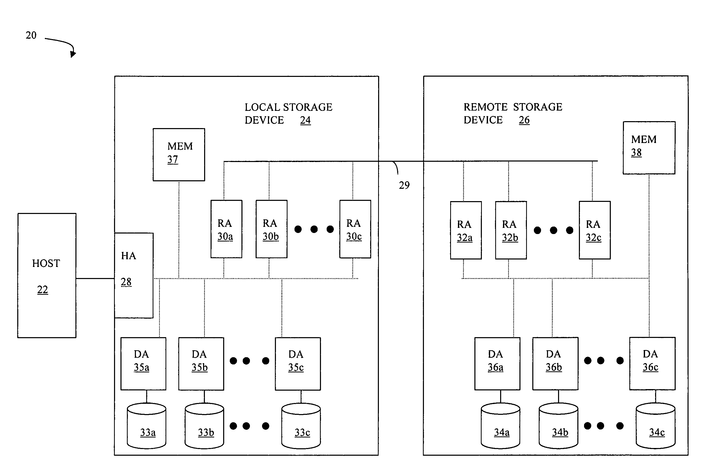
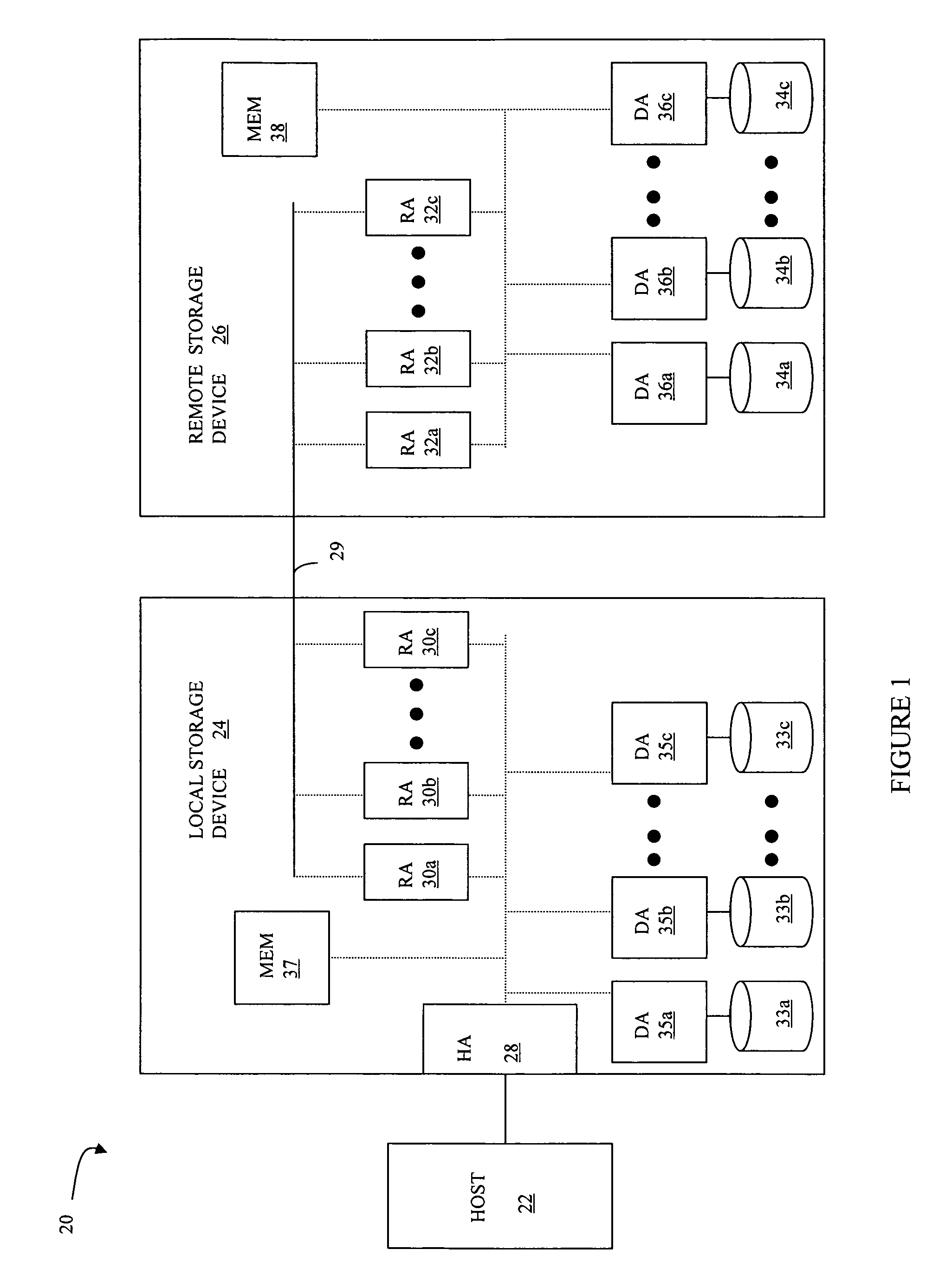
[0065]Referring to FIG. 1, a diagram 20 shows a relationship between a host 22, a local storage device 24 and a remote storage device 26. The host 22 reads and writes data from and to the local storage device 24 via a host adapter (HA) 28, which facilitates the interface between the host 22 and the local storage device 24. Although the diagram 20 only shows one host 22 and one HA 28, it will be appreciated by one of ordinary skill in the art that multiple HA's may be used and that one or more HA's may have one or more hosts coupled thereto.

[0066]Data from the local storage device 24 is copied to the remote storage device 26 via an RDF link 29 to cause the data on the remote storage device 26 to be identical to the data on the local storage device 24. Although only the one link 29 is shown, it is possible to have additional links between the storage devices 24, 26 and to have links between one or both of the storage devices 24, 26 and other storage devices (not shown). In addition, t...


PUM


Abstract

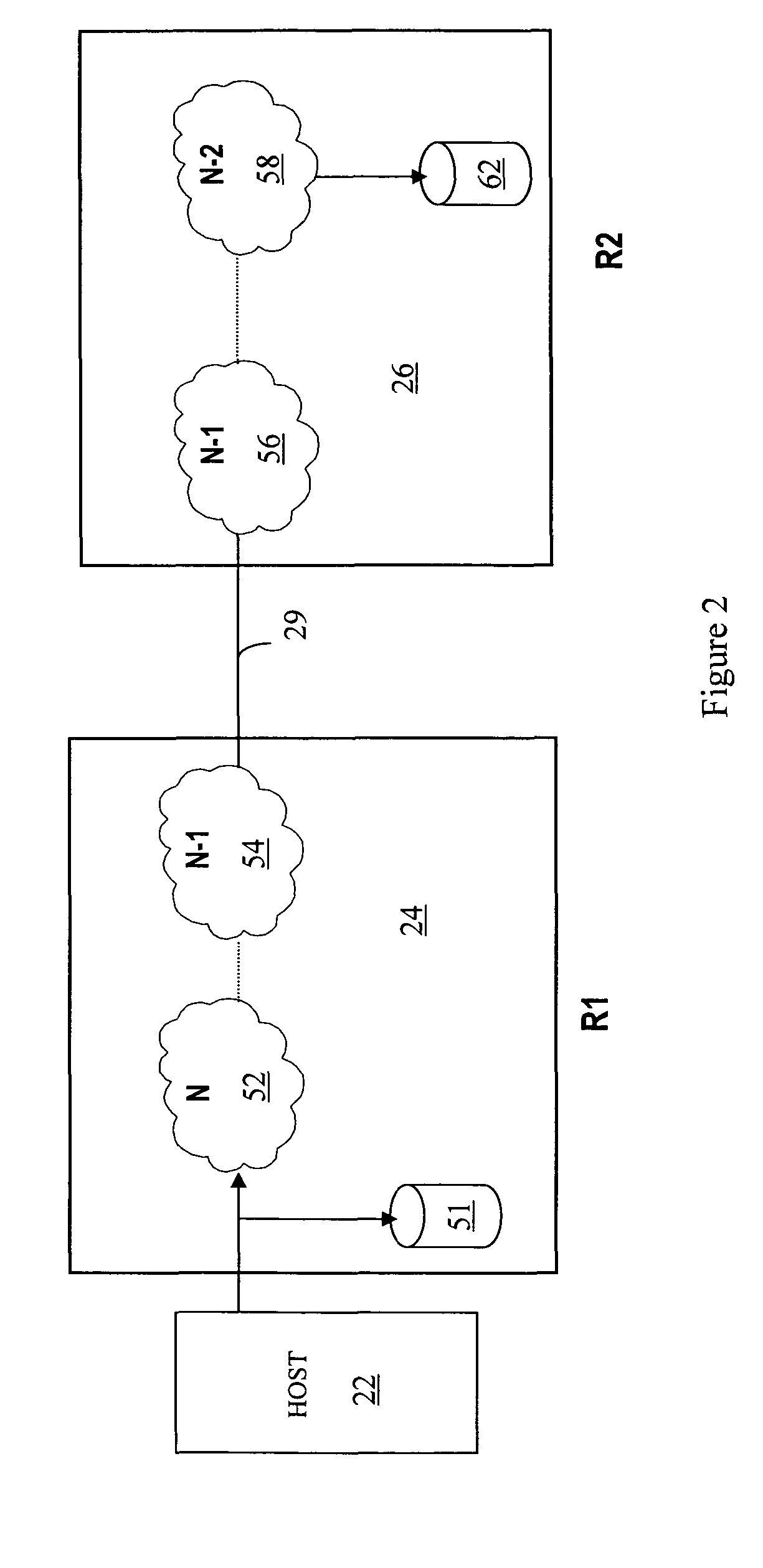
Storing recovery data includes providing chunks of data to a remote destination, where each chunk of data represents data written before a first time and after a second time and where the second time for one of the particular chunks corresponds to a first time for a subsequent one of the particular chunks, providing synchronous data to a local destination, and providing an indicator to the local destination in connection with creation of a new chunk of data for storage at the remote destination. The local destination may maintain a plurality of maps, where each of the maps associates synchronous data being provided thereto with a specific chunk of data. In response to receiving an indicator in connection with creation of a new chunk of data, the local destination may point to a new map. There may be two maps or more than two maps.

Description

BACKGROUND OF THE INVENTION[0001]1. Technical Field[0002]This application relates to computer storage devices, and more particularly to the field of transferring data between storage devices.[0003]2. Description of Related Art[0004]Host processor systems may store and retrieve data using a storage device containing a plurality of host interface units (host adapters), disk drives, and disk interface units (disk adapters). Such storage devices are provided, for example, by EMC Corporation of Hopkinton, Mass. and disclosed in U.S. Pat. No. 5,206,939 to Yanai et al., U.S. Pat. No. 5,778,394 to Galtzur et al., U.S. Pat. No. 5,845,147 to Vishlitzky et al., and U.S. Pat. No. 5,857,208 to Ofek. The host systems access the storage device through a plurality of channels provided therewith. Host systems provide data and access control information through the channels to the storage device and the storage device provides data to the host systems also through the channels. The host systems do no...

Claims


Application Information

Patent Timeline
Patent Type & Authority Patents(United States)
IPC IPC(8): G06F13/00
CPCG06F11/2058G06F11/2069G06F11/2074G06F11/2079G06F11/2082G06F11/2071G06F3/0619G06F3/065G06F3/067
Inventor LECRONE, DOUGLAS E.COX, GARY H.QUINN, BRETT A.MEIRI, DAVIDHALSTEAD, MARK J.YODER, BENJAMIN W.
Owner EMC IP HLDG CO LLC
Learn More