Footwear

a technology for footwear and arch supports, applied in the field of footwear, can solve the problems of reducing lateral stability, unable to properly address the component of gait associated with the forefoot, and little control of arch support in the transfer of weigh

Active Publication Date: 2011-12-20
ROSA ADRIANO
View PDF13 Cites 61 Cited by
  • Summary
  • Abstract
  • Description
  • Claims
  • Application Information

AI Technical Summary

Benefits of technology

[0009]In another embodiment, a shoe for supporting a wearer's foot upon a surface includes a sole, a lateral stabilizer pedestal, a medial stabilizer pedestal, a heel pedestal, and an array of forefoot support pads. The sole includes a forefoot portion associated with a plantar region of a wearer's foot, a midfoot portion associated with a wearer's arch, and a heel portion associated with a wearer's heel. The lateral stabilizer pedestal extends from the midfoot portion at least partially beneath a wearer's cuboid bone. The medial stabilizer pedestal extends from the midfoot portion at least partially beneath a wearer's navicular bone. The heel pedestal extends from the heel portion beneath a wearer's heel. The array of forefoot support pads includes at least a first forefoot support pad adjacent the lateral stabilizer pedestal and the medial stabilizer pedestal, and a second forefoot support pad adjacent the front of the shoe. The array of forefoot support pads is integrated into and extends fr

Problems solved by technology

Merely adjusting the arch support may affect a small component of a person's gait, but it cannot properly address the component of gait associated with the forefoot, i.e. supporting full body weight on the plantar portion of the foot, and pushing off to transfer the body weight to the other foot.
An arch support does little to properly control the transfer of weight from the heel to the midfoot and thence to the forefoot that occurs while taking a step.
While this may provide a wider base on which to support a person's w

Method used


Image

  • Footwear
  • Footwear
  • Footwear

Examples


Embodiment Construction

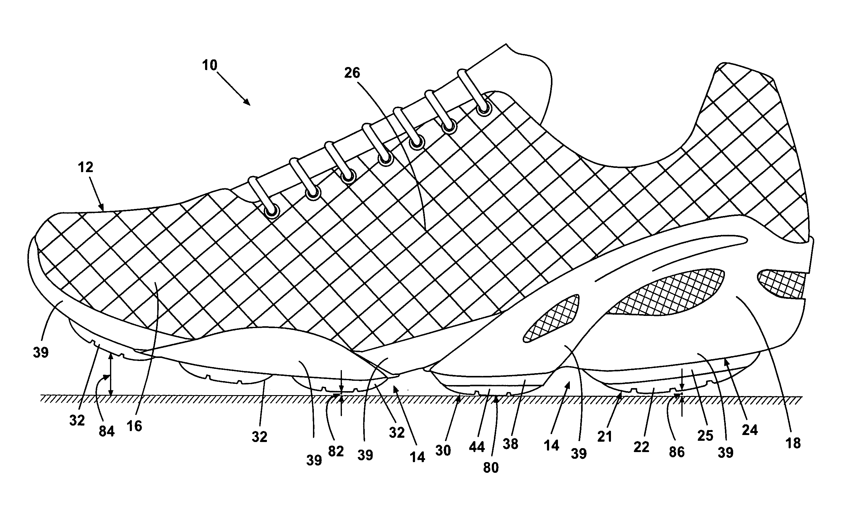
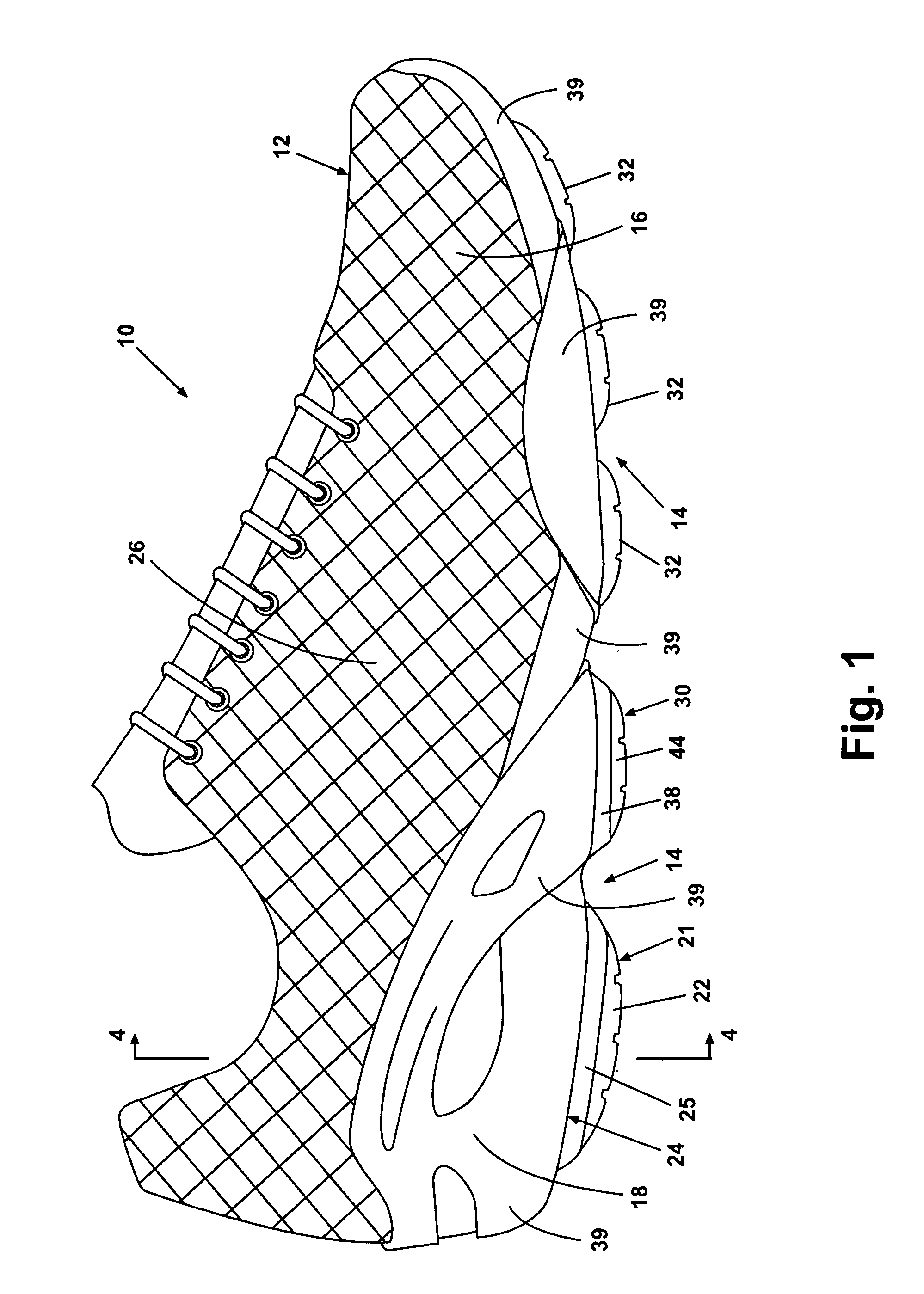
[0021]Referring to FIG. 1, an embodiment of the invention is illustrated comprising a shoe 10 having a generally known upper portion 12. The shoe 10 has a forefoot portion 16, such as a toe box, a midfoot portion 26 associated with a wearer's arch, and a heel portion 18, such as a heel cradle. The shoe 10 is illustrated as an athletic, lace-up style. However, the shoe 10 can be of any selected style.

[0022]Referring also to FIG. 2, the shoe 10 has a sole 14 comprising a platform 20. The forefoot portion of the sole 14 comprises an array of forefoot support pads 32 integrated therein and extending away from the platform 20 for cushioning the forefoot, and providing fraction and lateral stability. FIG. 2 illustrates an exemplary distribution and configuration of the support pads 32. However, the configuration and distribution of the support pads 32 can be selected based upon factors such as shoe flexibility, weight distribution in the forefoot portion, degree of cushioning, and the lik...


PUM


Abstract

A shoe has a sole including a platform for supporting a wearer's foot upon a surface. The shoe includes a heel pedestal extending from the platform beneath a wearer's heel, a lateral stabilizer pedestal extending from the platform at least partially beneath a wearer's cuboid bone, and a medial stabilizer pedestal extending from the platform at least partially beneath a wearer's navicular bone. The heel pedestal, the lateral stabilizer pedestal, and the medial stabilizer pedestal include an outsole for contacting the surface, a compressible middle layer between the outsole and the wearer's foot, and a base layer between the middle layer and the wearer's foot having a compressibility that is lower than the compressibility of the middle layer.

Description

[0001]This application claims the benefit of U.S. provisional application Ser. No. 60 / 893,273, filed Mar. 6, 2007, which is incorporated herein in its entirety.BACKGROUND OF THE INVENTION[0002]The invention relates generally to footwear, and specifically to footwear adapted to adjust posture and gait associated with different foot physiologies.[0003]A significant number of people require some type of insert or other orthotic device to address anomalies in foot physiology and gait. Typically, addressing such anomalies consists of no more than a static adjustment of the arch support, or stabilization of the heel, or both. Little if any attention is paid to the forefoot, or the person's gait, when addressing foot anomalies.[0004]Merely adjusting the arch support may affect a small component of a person's gait, but it cannot properly address the component of gait associated with the forefoot, i.e. supporting full body weight on the plantar portion of the foot, and pushing off to transfe...

Claims


Application Information

Patent Timeline
IPC IPC(8): A43B13/00
CPCA43B7/142A43B7/1425A43B7/143A43B7/1435A43B7/144A43B7/16A43B13/12A43B13/143A43B13/186A43B23/081
Inventor ROSA, ADRIANO
Owner ROSA ADRIANO
Why Eureka
Try Eureka