Adjustable weights for model race car

a technology for race cars and weights, applied in toys, entertainment, toys, etc., can solve the problems of cumbersome and difficult to continuously attach and remove weights from cars, and achieve the effect of quick and easy variation of the center of gravity

Active Publication Date: 2011-12-27
OSMENT DAVID L
View PDF6 Cites 7 Cited by
  • Summary
  • Abstract
  • Description
  • Claims
  • Application Information

AI Technical Summary

Benefits of technology

[0008]The present invention is an adjustable weight system that allows a model race car builder to quickly and easily vary the center of gravity and front and rear axle weights of their model race car. In accordance with one embodiment of the present invention, the adjustable weight system is for use with an object having a bore surrounded by a bore surface, and most preferably is for use within a bore formed in the chassis of a model race car. The system comprises a cylinder that is configured to be positioned within the bore. The cylinder has a side wall, opposing end walls joined with the side wall, screw threads that are integral with the side wall and configured to form complemental threads in the bore surface, and a structure associated with one of the end walls for engaging a tool for adjustably positioning the cylinder within the bore and forming the complemental threads.
[0009]Most preferably, the structure associated with one of the end walls comprises an opening configured to receive the end of a tool for rotating the cylinder within the bore. Preferably, a protrusion extends from the end wall that is opposite the end wall with the opening. The opening is configured to receive the protrusion so that multiple weights may be interlocked for quickly increasing or decreasing the weight of a model race car. Preferably, when two or more weights are interlocked, the mated protrusions and openings are configured so that the threads on each of the weights are aligned thereby ensuring they will engage the same complemental threads formed in the bore surface. Preferably, the protrusion comprises a spline that is configured to be received by a groove in the opening for ensuring that the threads on two interlocked weights are aligned.

Problems solved by technology

While this testing is preferable in order to determine the optimum position for the weights, it is difficult and cumbersome to continuously affix and remove the weights from the car.

Method used


Image

  • Adjustable weights for model race car
  • Adjustable weights for model race car
  • Adjustable weights for model race car

Examples


Embodiment Construction

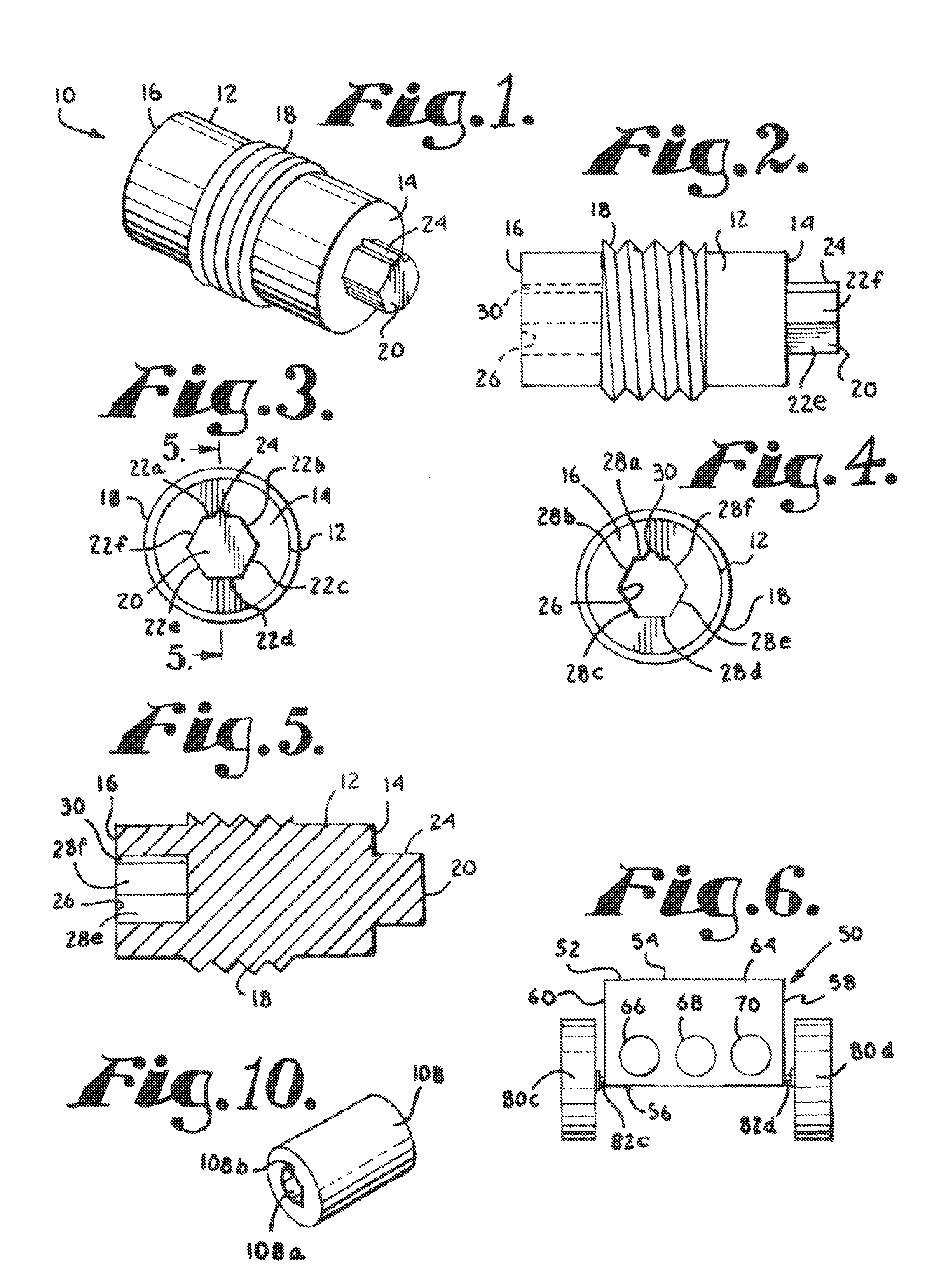
[0024]A weight according to the preferred embodiment of the present invention is shown generally as 10 in FIG. 1. As shown in FIGS. 1-4, the weight 10 is a cylinder having a side wall 12 and opposing end walls 14 and 16 that are each joined with the side wall 12. The weight has male screw threads 18 that are integrally formed with the side wall 12. As shown in FIG. 3, the screw threads 18 have a major diameter that is slightly greater than the cross-sectional diameter of the side wall 12.

[0025]Referring to FIG. 3, a hexagonal protrusion 20 having sides 22a-f is joined with and extends outward from end wall 14. A spline 24 is joined with and extends upward from side 22a. Referring to FIG. 4, end wall 16 presents a hexagonal opening 26 for accessing a recess within cylinder 12 that is surrounded by side walls 28a-f. There is a groove 30 in side wall 28a. Opening 26 and groove 30 are sized slightly larger than protrusion 20 and spline 24 such that the opening 26 and groove 30 can recei...


PUM


Abstract

An adjustable weight system and method for adjusting the center of gravity and front and rear axle weights of a model race car. The adjustable weight system includes a cylinder having screw threads that are configured to form complemental threads in a surface surrounding a bore of an object that the cylinder is placed within. The cylinder is configured to engage a tool for adjustably positioning the cylinder within the bore and forming the complemental threads. The methods for adjusting the center of gravity and front and rear axle weights each include selecting a desired center of gravity location, front axle weight, or rear axle weight, placing at least a front or rear wheel of the car on a scale, and moving an adjustable weight on the car's chassis until the desired and actual center of gravity, front axle weight, or rear axle weight are approximately equal.

Description

CROSS-REFERENCE TO RELATED APPLICATIONS[0001]Not Applicable.STATEMENT REGARDING FEDERALLY SPONSORED RESEARCH OR DEVELOPMENT[0002]Not Applicable.BACKGROUND OF THE INVENTION[0003]1. Field of the Invention[0004]The present invention relates to an adjustable weight system and method, and more particularly, to an adjustable weight system and method for adjusting the center of gravity and front and rear axle weights of a model race car.[0005]2. Description of Related Art[0006]The Pinewood Derby® is an annual competition for which children design and build model race cars. Each child is typically provided with a kit including a wooden block, four plastic wheels, and four small nails. The block is formed into the car's chassis and the nails are used as axles to affix the wheels to the car. The race track used for the derby consists of an inclined section which transitions into a horizontal section. The start line is at the top of the inclined section and the finish line is at the end of the...

Claims


Application Information

Patent Timeline
Patent Type & Authority Patents(United States)
IPC IPC(8): A63H27/32A63H27/00
CPCA63H17/262
Inventor FULTON, C. DWAYNE
Owner OSMENT DAVID L
Why Eureka
Try Eureka