Eureka AIR delivers breakthrough ideas for toughest innovation challenges, trusted by R&D personnel around the world.

Overvoltage protection element

a protection element and overvoltage protection technology, applied in the direction of overvoltage protection resistors, emergency protection arrangements for limiting excess voltage/current, overvoltage protection resistors, etc., can solve the problem of unwanted increase of leakage current of varistor at operating voltage, electrical disconnection of varistor, and opening contact of varistor can produce arcs at operating voltages greater than, so as to improve the protection element and improve the overvoltage protection effect, the effect of reliable and durabl

Active Publication Date: 2012-01-03
PHOENIX CONTACT GMBH & CO KG
View PDF14 Cites 5 Cited by
  • Summary
  • Abstract
  • Description
  • Claims
  • Application Information

AI Technical Summary

Benefits of technology

[0014]The above and other objects are achieved by providing an improved overvoltage protection element, including a housing having two metal shells, with one of the two shells being electrically connected to a terminal region of an arrester. By making the two housing halves or housing shells of metal, advantageously, reliable and durable encapsulation of the arrester, which can include a varistor, located within the housing is achieved. In addition, if, as a result of overloading of the varistor, ignition of an arc or destruction of the varistor occurs, this does not lead to damage to devices adjacent to or outside of the overvoltage protection element, due to the durable metal encapsulation of the arrester. Suppressor diodes, gas-filled surge diverters, and the like, also can be used for the arresters, and being advantageous, especially when using varistors as the arresters. Accordingly, the term varistor is used interchangeably for arrester herein, and without limiting the invention in any respect.

Problems solved by technology

As a result of ageing and temporary overvoltages (TOV) in the range of seconds, especially in overvoltage protection elements with a varistor as the arrester, an unwanted increase of the leakage current of the varistor at operating voltages occurs.
In known overvoltage protection elements, the state of the varistor is monitored according to the principle of a temperature switch, so that when the varistor overheats, for example, due to leakage currents, a solder connection provided between the varistor and a separating means is broken, leading to electrical disconnection of the varistor.
However, a disadvantage of such known overvoltage protection devices and overvoltage protection elements is that each opening contact thereof can produce an arc at operating voltages greater than 30 volts and at high current loads.
Thus, when the solder connection is broken, an arc can occur between the varistor and the separating means, and which can lead to damage of components located within the overvoltage protection element, or to damage of the overvoltage protection element itself, especially to the plastic housing which surrounds the varistor.
Since such overvoltage protection elements or overvoltage protection devices are often located with several adjacent to one another or to other electronic devices in a switchgear cabinet, an arc which occurs within the housing, can cause adjacent overvoltage protection devices or other electronic devices also to be destroyed or damaged.
Although making the housing from aluminum does prevent destruction of the housing when an arc occurs on the varistor, the making of electrical contact of the varistor and its arrangement in the housing, and the arrangement and configuration of the electrodes, especially the necessity of routing the electrodes for electrical connection through the housing cover or the end caps electrically insulated from the outside, make such a structure and installation of such an overvoltage protection device relatively complex.

Method used


Image

  • Overvoltage protection element
  • Overvoltage protection element
  • Overvoltage protection element

Examples


Embodiment Construction

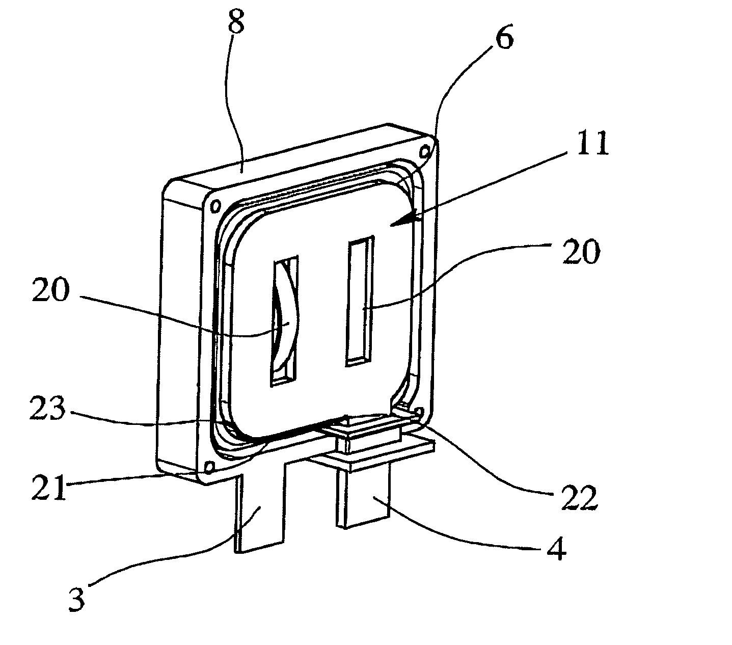
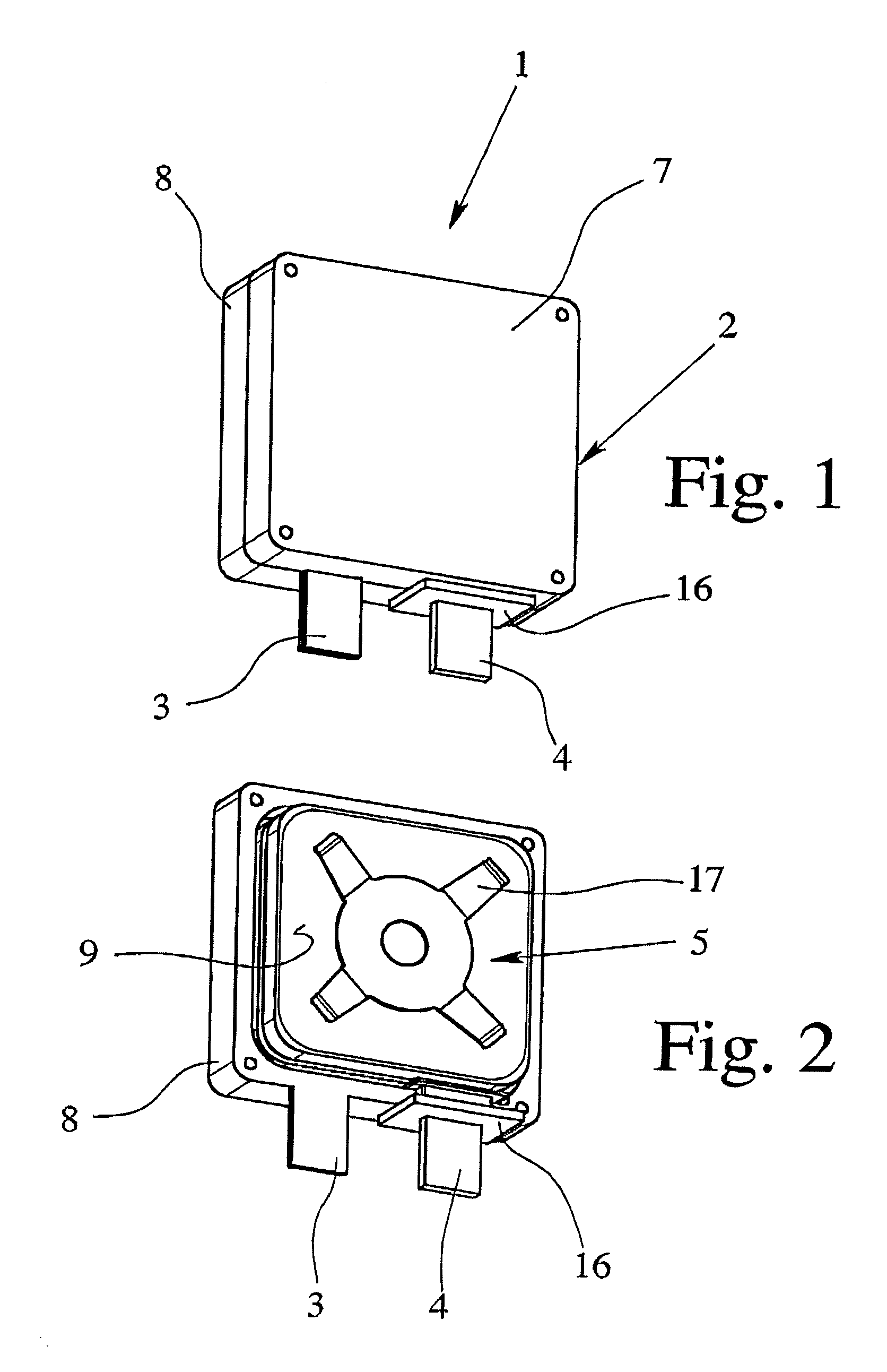
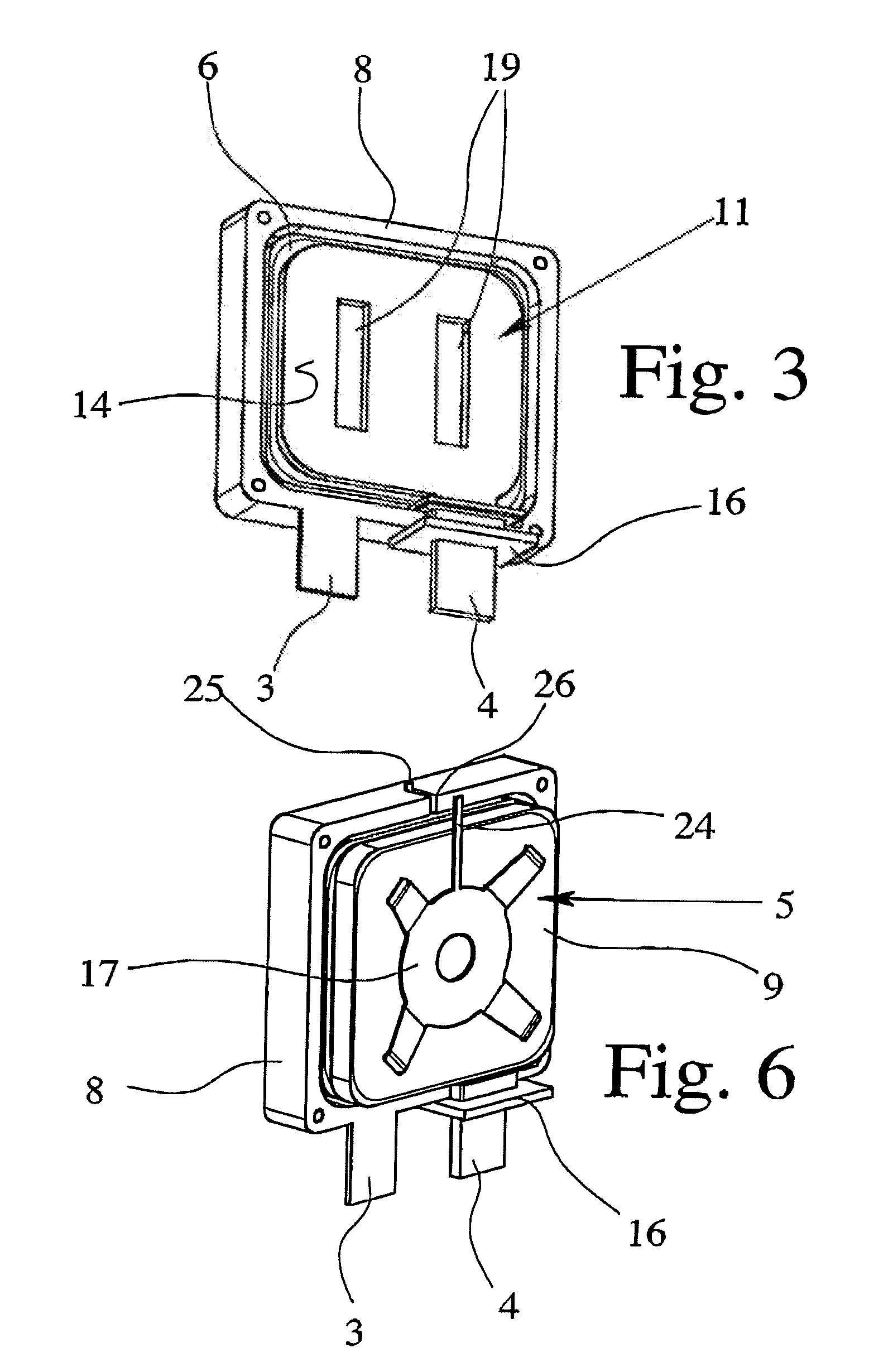
[0036]The overvoltage protection element 1 shown in FIGS. 1-6 can be made as a “protective plug” and which can be plugged into the corresponding bottom part of an overvoltage protection device. In addition to the overvoltage protection element 1 being part of a two-part overvoltage protection device, the overvoltage protection element can also be made as a one-piece overvoltage protection device (e.g., it need not have a separate bottom part).

[0037]The overvoltage protection element 1 can include a housing 2, two electrical terminals 3, 4 for electrical connection of the overvoltage protection element 1 to the current or signal paths to be protected, and two varistors 5, 6, which are connected electrically in parallel and which are located spatially in succession within the housing 2, and used as arresters. In further embodiments, however, a single varistor 5 can be employed within the housing 2.

[0038]The housing 2 has two metal shells 7, 8, each have one plug contact at a time, whi...


PUM


Abstract

An overvoltage protection element (1) includes a housing (2), two terminals (3, 4) for electrical connection of the overvoltage protection element (1) to current or signal paths to be protected, and an arrester (5, 6), including a varistor, located within the housing (2). In addition to providing a simple structure and installation, the overvoltage protection element (1) is especially well adapted to thermal and dynamic loads, so that no damage to the overvoltage protection element (1) occurs to the outside, wherein the housing (2) includes two metal shells (7, 8) electrically connected to a terminal region (9, 10) of the arrester (5, 6).

Description

BACKGROUND OF THE INVENTION[0001]1. Field of Invention[0002]The present invention relates to an overvoltage protection element including a housing and having at least two terminals for electrical connection of the overvoltage protection element to current or signal paths to be protected, and with at least one arrester, including a varistor, located within the housing.[0003]2. Description of Related Art[0004]Electrical circuits and systems normally work without problems using the voltage specified for them, that is, the rated voltage. This does not apply when overvoltages occur. Overvoltages are considered to be all voltages which are above the upper tolerance limit of the rated voltage. They also mainly include transient overvoltages which can occur due to atmospheric discharges, but also due to switching operations or short circuits in power supply grids, and can be galvanically, inductively or capacitively coupled into electrical circuits. In order to protect electrical or electro...

Claims


Application Information

Patent Timeline
Patent Type & Authority Patents(United States)
IPC IPC(8): H01C7/10H01C7/108H01C7/12
CPCH01C7/12
Inventor WOSGIEN, JOACHIM
Owner PHOENIX CONTACT GMBH & CO KG
Why Eureka
Eureka Blog
Learn More