Press machine

a press machine and frame technology, applied in the field of press machines, can solve the problems of overload, damage to the entire machine including the frame, and difficulty in estimating the load required for such forming, and achieve the effect of convenient installation

Active Publication Date: 2012-01-17
MURATA MASCH LTD
View PDF5 Cites 3 Cited by
  • Summary
  • Abstract
  • Description
  • Claims
  • Application Information

AI Technical Summary

Benefits of technology

[0008]It is an object of the present invention to provide a press machine which can precisely detect load acted on a frame and in which such a load detecting system can be easily installed.
[0009]It is another object of the present invention to simplify the load detecting system.

Problems solved by technology

When overload exceeding an allowable limit of the frame is imposed, each portion of the machine including the frame maybe damaged.
When performing punch working, which is defined as press working, load required for such punch working can be estimated from the thickness of a work and from the size of a portion to be punched, however, when performing forming, it is difficult to estimate load required for such forming, and overload may be applied.
However, the aim of providing the drive transmission system with the load detecting means is not to measure the load actually acted on the frame.
Further, since the position of the load detecting means moves at the time of press working, it may be difficult to install wiring for acquiring the output of the load detecting means.

Method used


Image

  • Press machine
  • Press machine
  • Press machine

Examples


first embodiment

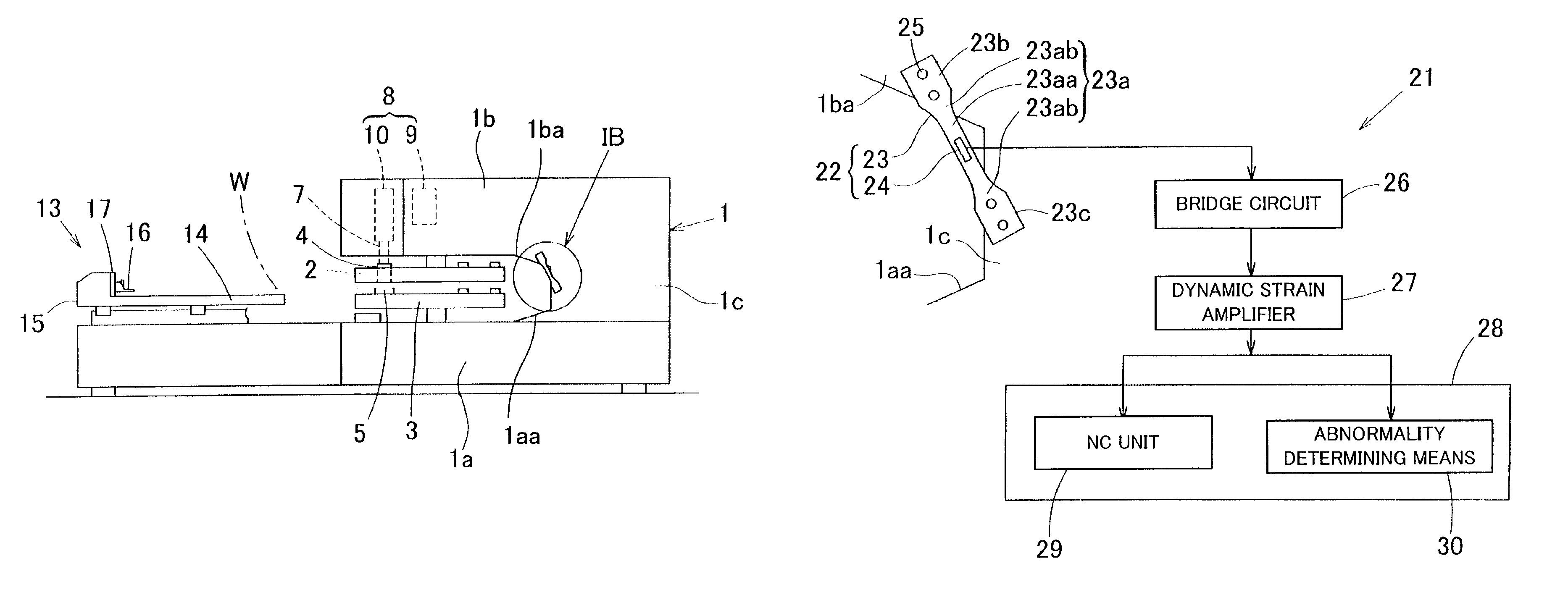
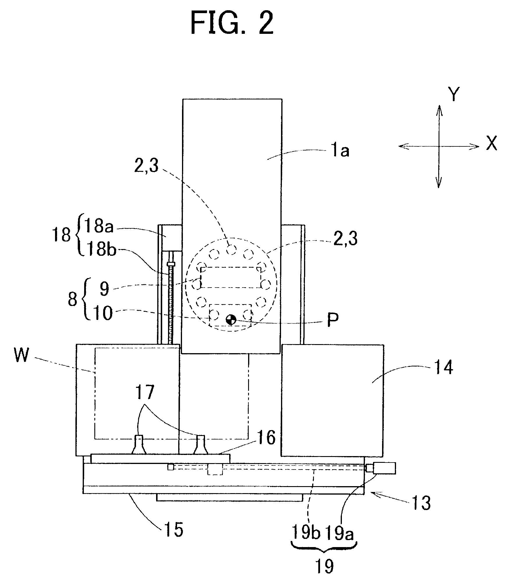
[0030]the present invention will be described with reference to the drawings. A press machine according to the present embodiment is a punch press. FIG. 1(A) is an entire side view, FIG. 2 is an entire plan view, and FIG. 3 is a perspective view of a frame. The punch press includes a frame 1 having a C shape in side view. More specifically, the frame 1 includes a lower horizontal frame 1a extending horizontally along the floor, an upper horizontal frame 1b that is arranged above the lower horizontal frame 1a and extends in the same direction as the lower horizontal frame 1a, and a vertical frame 1c arranged to vertically connect one end of the lower horizontal frame 1a and one end of the upper horizontal frame 1b. The upper horizontal frame 1b is in a cantilever state, and space is provided below the upper horizontal frame 1b, where later-described turrets 2 and 3 are arranged. A lower portion on a base side of the upper horizontal frame 1b includes a slanted portion 1ba where a low...


PUM


Abstract

A press machine is provided that can accurately detect load acted on a frame. A frame 1 includes an upper horizontal frame 1b, a lower horizontal frame 1a, and a vertical frame 1c arranged to connect the upper horizontal frame 1b and the lower horizontal frame 1a. A press drive mechanism 8 is provided to the upper horizontal frame 1b. A strain generation member 23 is arranged across from the upper horizontal frame 1b to the vertical frame 1c. In the strain generation member 23, an intermediate portion 23a has a cross-sectional area that is smaller than those of end portions 23b, 23c fixed to the upper horizontal frame 1b and the vertical frame 1c, respectively. A strain amount detecting body 24 is attached to the intermediate portion 23a of the strain generation member 23 in order to detect a strain amount.

Description

BACKGROUND OF THE INVENTION[0001]1. Field of the Invention[0002]The present invention relates to a press machine such as a punch press or the like that can detect load acted on a frame.[0003]2. Description of the Related Art[0004]When a punch press performs press working, load is imposed on a frame of the punch press. When overload exceeding an allowable limit of the frame is imposed, each portion of the machine including the frame maybe damaged. When performing punch working, which is defined as press working, load required for such punch working can be estimated from the thickness of a work and from the size of a portion to be punched, however, when performing forming, it is difficult to estimate load required for such forming, and overload may be applied.[0005]In order to prevent a machine abnormality resulted from overload, Patent Document 1 suggests to provide a drive transmission system arranged between a drive source and a punch tool of a press driving device with load detect...

Claims


Application Information

Patent Timeline
Patent Type & Authority Patents(United States)
IPC IPC(8): B30B15/28B30B15/00
CPCB30B15/047
Inventor FUKAMI, YASUHIKOYAMANE, KIYOSHI
Owner MURATA MASCH LTD
Why Eureka
Try Eureka