I-beam seismic sway brace clamp

a technology of sway braces and beams, which is applied in the field of ibeams, can solve the problems of slipping of the nut brackets off the rods and being lost, and achieve the effect of removing bending moments

Inactive Publication Date: 2012-01-24
ERICO INT
View PDF90 Cites 7 Cited by
  • Summary
  • Abstract
  • Description
  • Claims
  • Application Information

AI Technical Summary

Benefits of technology

[0006]An I-beam clamp includes a cast ductile iron bracket (a clamp bracket) with an acute angled opening, which the lower flange of an I-beam or similar structure fits into. Perpendicular to this opening is a tapped hole that accepts an engineered hardened cone tip screw. This screw bites into the top face of the lower flange of the I-beam when tightened. To insure proper biting force, the head of the screw is designed to snap off at a predetermined torque. In addition, a single tapped hole in the clamp bracket, coaxial to the engineered screw hole, is used for the mounting of seismic sway bracing or other objects. The coaxial position of the mounting hole helps to remove bending moments that would occur otherwise in the clamp bracket when loaded. Two clearance holes in the clamp bracket allow threaded rods to pass through to the rear bracket assembly. The rods are held in place with shear nuts designed with heads that snap off at a predetermined torque.
[0007]A rear bracket (nut bracket), also made of cast ductile iron, has the same acute angle opening that faces towards the clamp bracket's opening. The angles of both openings allow the brackets to grasp onto I-beams of varying flange thicknesses and shapes. The clamp bracket and nut bracket have a series of steps designed to provide contact points above flanges of different thicknesses. These steps prevent excessive rotation of the clamp and nut brackets as they are tightened against the flange. The nut bracket also has two half female threads with through holes located concentrically behind them. These female threads give the nut bracket the ability to engage and disengage the threaded rods. This ability allows the installer to quickly traverse the nut bracket inward along the axis of the rods without having to rotate the rods. The concentric through holes on the nut bracket help to contain the threaded rods when they are disengaged from the female thread. The diameter of the through hole relative to the minor female thread diameter is such that the rod will have enough vertical movement to completely disengage the female thread. These holes also remove the rotational degree of freedom, insuring that the nut bracket will always be positioned correctly relative to the clamp bracket. By itself, the nut bracket could be used to clamp on to an I-beam. This would occur when the rods are forced to engage the female threads by the bottom face of the I-Beam flange and the top of the flange is contacting the angled opening. This motion clamps the rods tightly against the female threads and insures that the rear bracket will now always act like a nut. Unfortunately, when the I-beam is not engaged, the nut bracket could slide off of the rods and be lost. To account for this, the nut bracket assembly also incorporates a spring mechanism that engages and disengages the threaded rod with the female thread. The spring is mounted to the nut bracket with a rivet, and has two wings that push down on top of the threaded rods. This mechanism enables the rear bracket to act as a nut when the threads are engaged without the contact of the I-beam and a through hole when disengaged.
[0012]According to a further aspect of the invention, a clamp, such as a clamp for engaging a lower flange of an I-beam, includes a series of steps on the faces of the acute angle brackets prevent excessive rotation of the brackets as they are tightened against flanges of different thicknesses.
[0016]According to still another aspect of the invention, in a clamp the coaxial position of the mounting hole relative to the screw hole removes bending moments that would occur otherwise when the clamp bracket is loaded.
[0019]According to another aspect of the invention, a clamp applies pressure to both sides of a beam flange while the hardware use to secure the assembly is only on one side: this enables the installer to tighten hardware with tools on only one side of the beam.
[0020]According to yet another aspect of the invention, a clamp includes wings on a clamp bracket, located underneath (in contact with) threaded rods, to help control the freedom of movement of the rods. This limits the magnitude of the bracket not mounting flush to the bottom of an I-beam.

Problems solved by technology

Unfortunately, when the I-beam is not engaged, the nut bracket could slide off of the rods and be lost.

Method used


Image

  • I-beam seismic sway brace clamp
  • I-beam seismic sway brace clamp
  • I-beam seismic sway brace clamp

Examples


Embodiment Construction

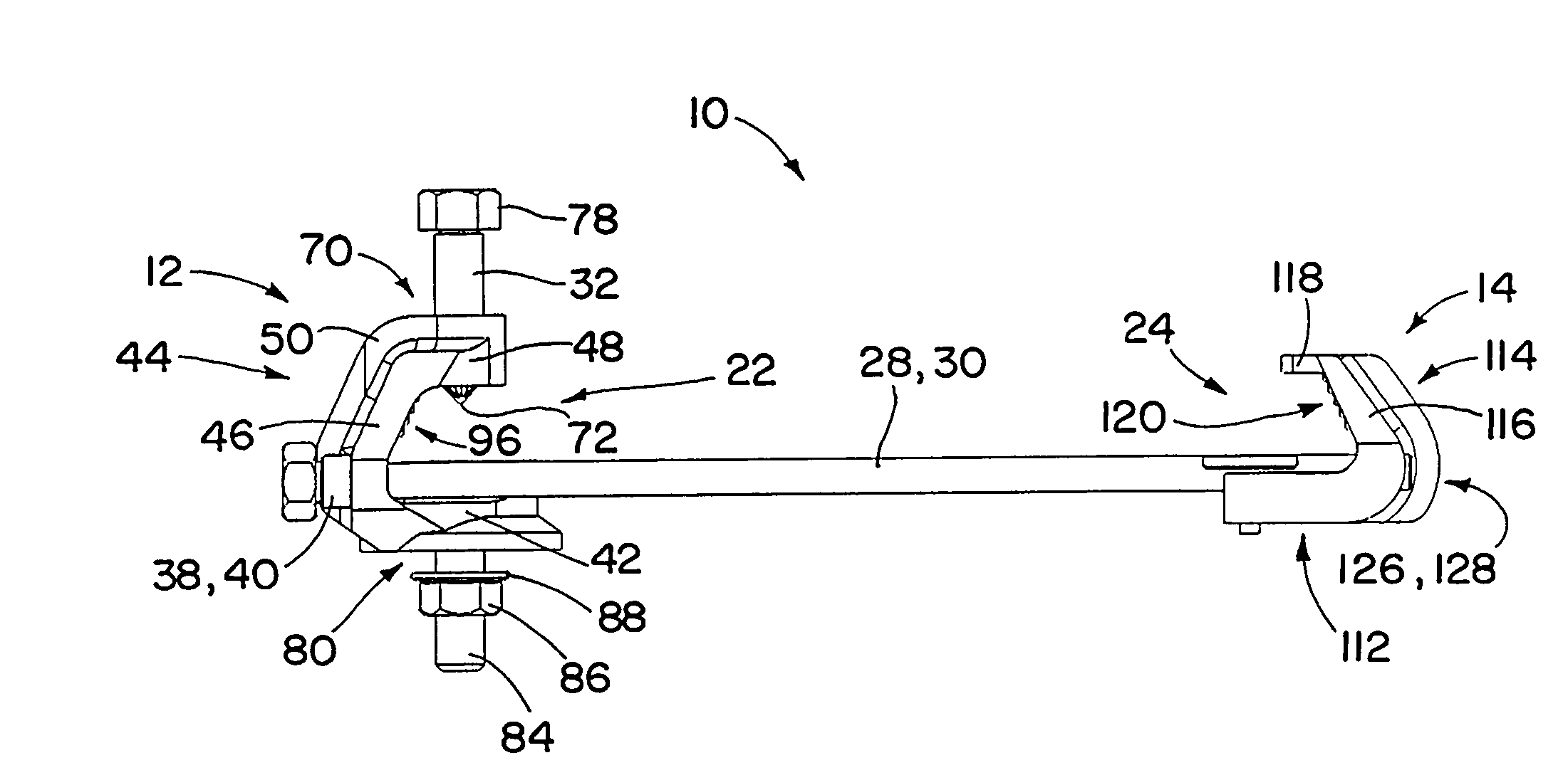
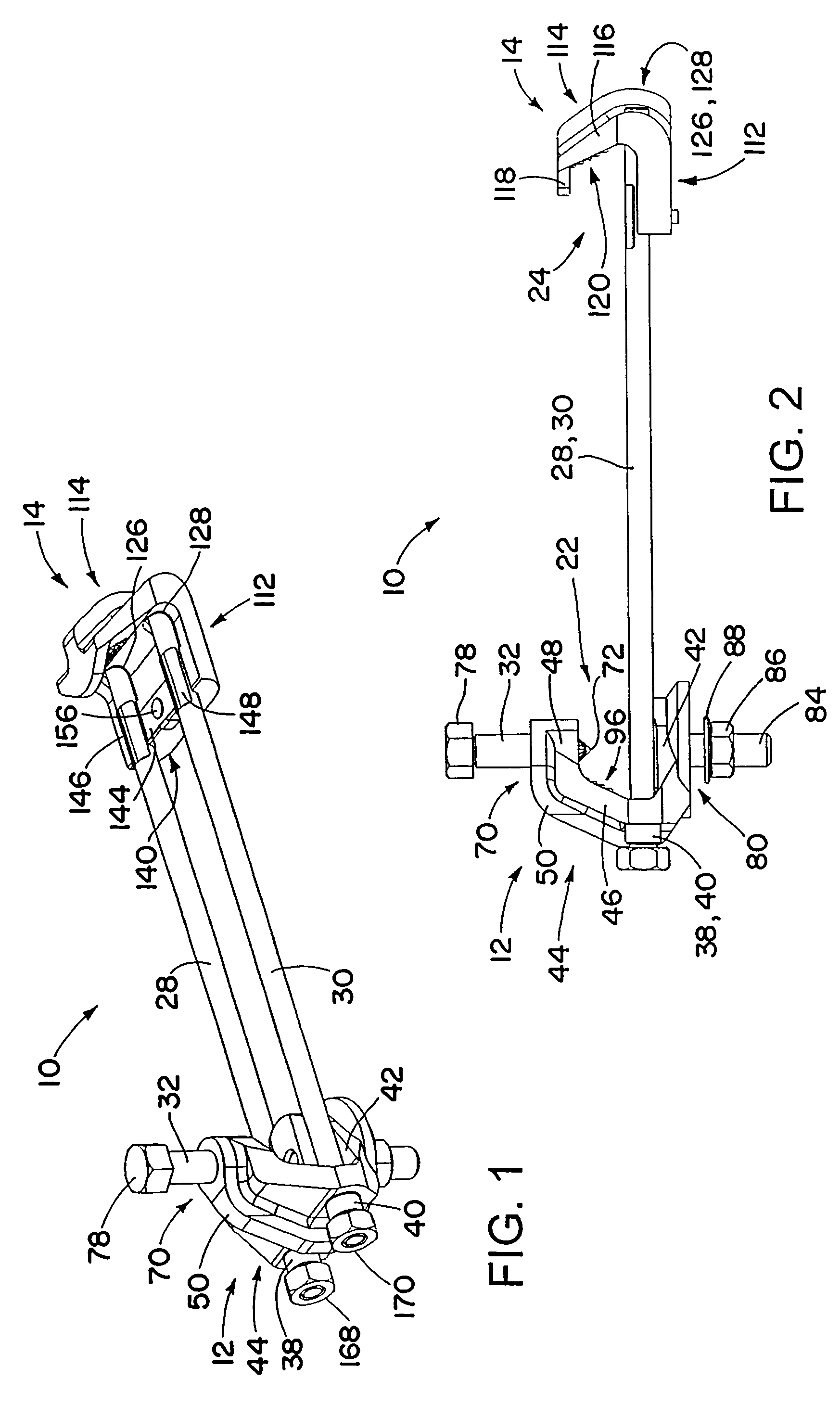
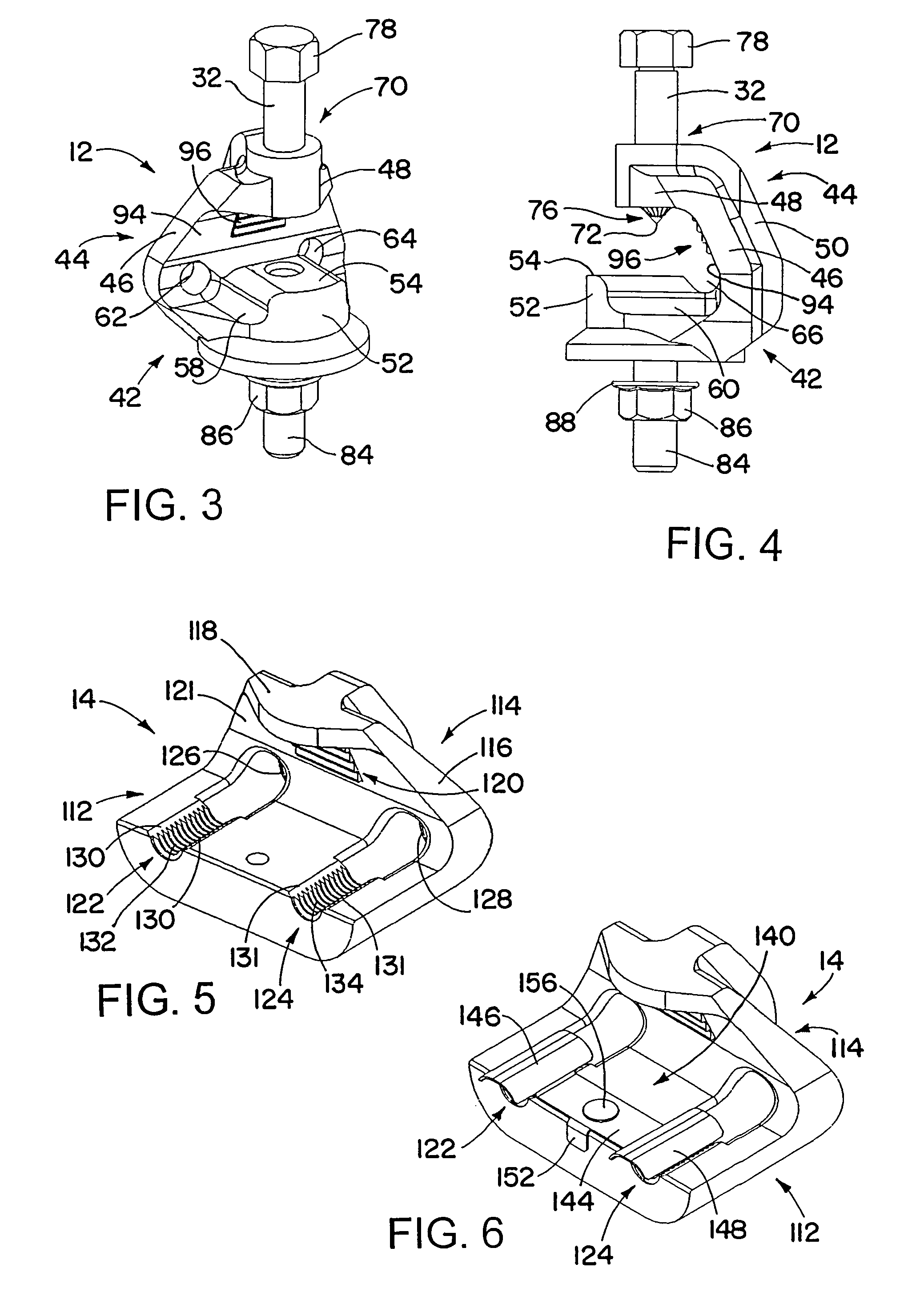
[0038]An I-beam clamp, used for engaging the flange of an I-beam, bar joist, or other structural member includes a pair of threaded rods and a pair of brackets that can be moved relative to each other along the threaded rods. The brackets have respective angled openings for engaging opposite ends of the I-beam. The brackets also have steps on inner surfaces facing the angled openings, for engaging I-beam flanges having different thicknesses. One of the brackets, a clamp bracket, has a set screw configured to engage a top surface of the I-beam flange, to hold the clamp in place once it is installed on the I-beam. The clamp bracket also has a mounting hole for mounting or suspending objects, such as sway braces, from the I-beam clamp. The hole for the set screw and the mounting hole may be substantially coaxial. The other of the brackets, a nut bracket, has half-threaded portions for selectively engaging the threaded rods, to hold the nut bracket in place relative to the threaded rods...


PUM


Abstract

An I-beam clamp, used for engaging the bottom flange of an I-beam or bar joist, includes a pair of threaded rods and a pair of brackets that can be moved relative to each other along the threaded rods. One of the brackets, a clamp bracket, has a set screw configured to engage a top surface of the I-beam flange, to hold the clamp in place once it is installed on the I-beam. The other of the brackets, a nut bracket, has half-threaded portions for selectively engaging the threaded rods, to hold the nut bracket in place relative to the threaded rods, and to disengage from the threaded rods, in order to allow positioning of the nut bracket along the threaded rods. The nut bracket may include a spring clip or other device to provide force to bias into engagement the threaded rods with the half-threaded portions.

Description

[0001]This application claims priority under 35 USC 119 from U.S. Provisional Application No. 61 / 022,406, filed Jan. 21, 2008, which is incorporated herein by reference in its entirety.BACKGROUND OF THE INVENTION[0002]1. Field of the Invention[0003]The invention is in the field of attachments to I-beams, such as for use in seismic bracing, sway bracing, structure attachment fitting, and seismic restraint.[0004]2. Description of the Related Art[0005]Seismic sway bracing is often required for plumbing systems, fire sprinklers, electrical systems, heating conduits, ventilation conduits, air conditioning conduits, and other structural and non-structural components of a building as well as some equipment installed in buildings. One way of sway bracing is to couple a system to be braced to a pipe or other rigid structural member that is in turn coupled to building structure, such as a wall or a building structural member. The common practice in mounting to the lower flange of an I-beam re...

Claims


Application Information

Patent Timeline
Patent Type & Authority Patents(United States)
IPC IPC(8): F16L3/24
CPCF16B2/065F16L3/16F24F13/0254F16L3/24F16L3/18
Inventor OSBORN, ERIC C.AMBROGIO, NICHOLAS J.WILSON, ERIC J.ALLEN, PAUL B.
Owner ERICO INT
Why Eureka
Try Eureka