
Leaf seal arrangement

a seal arrangement and leaf technology, applied in the direction of engine seals, machines/engines, metal-working devices, etc., can solve the problems of reducing the effective limiting the life of the seal arrangement, and rubbing hard on the rotating surface of the bristles

Active Publication Date: 2012-01-24
ROLLS ROYCE PLC
View PDF10 Cites 2 Cited by
  • Summary
  • Abstract
  • Description
  • Claims
  • Application Information

AI Technical Summary

Problems solved by technology

However, the disadvantage of brush seal bristles is that at high differential pressures, at which condition seals are most advantageous, the bristles exhibit two behaviours which limit their life.
One problem is blow down, which can cause the bristles to rub hard on a rotating surface.
Another problem is the tendency of the pressure force to lock the bristles against the seal backing ring which stops them from moving to accommodate for rotor excursions.
Both these disadvantages give rise to premature wear of a seal arrangement and therefore significantly reduce that seal arrangement's effective life.

Method used


Image

  • Leaf seal arrangement
  • Leaf seal arrangement
  • Leaf seal arrangement

Examples


Embodiment Construction

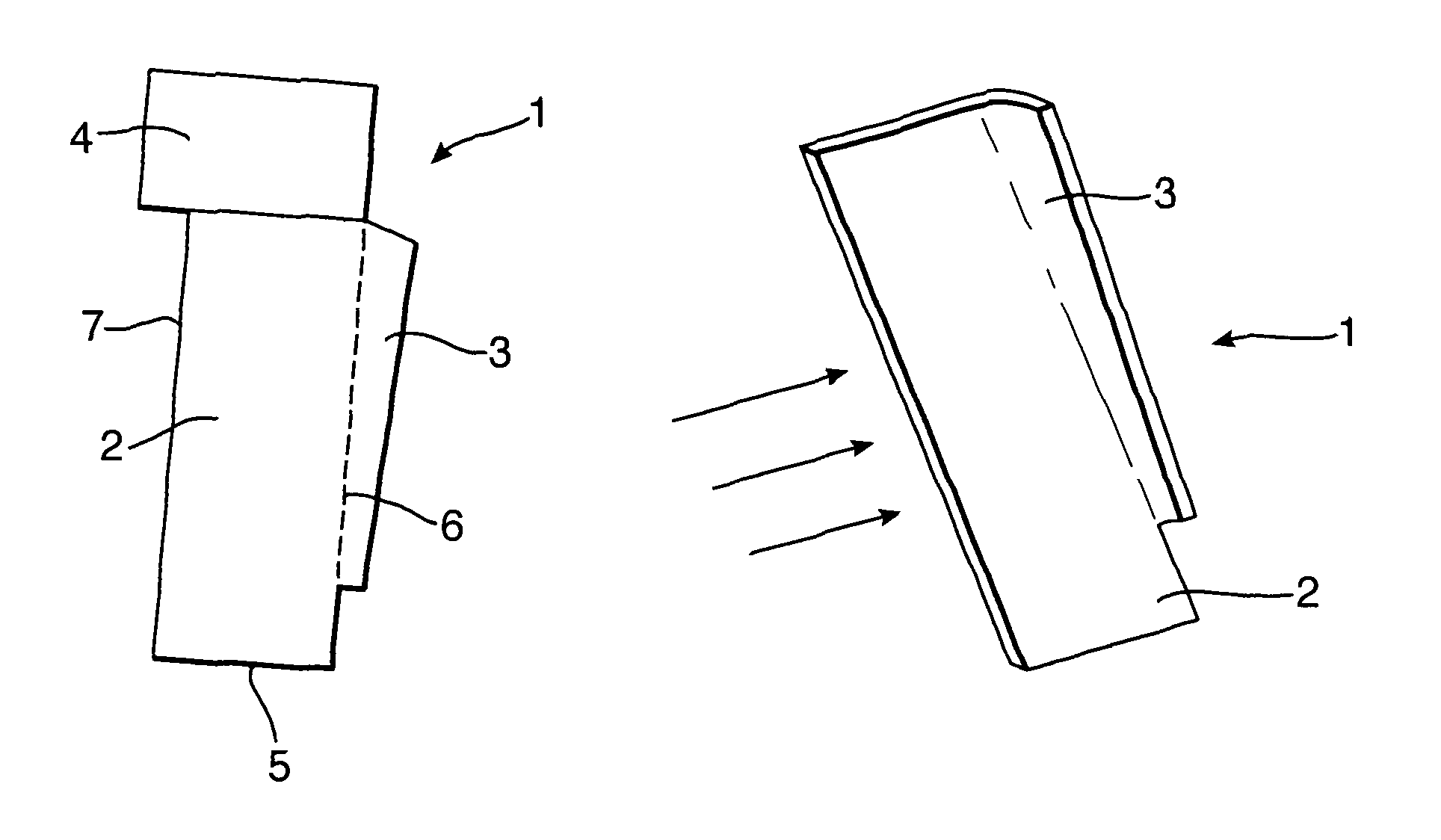
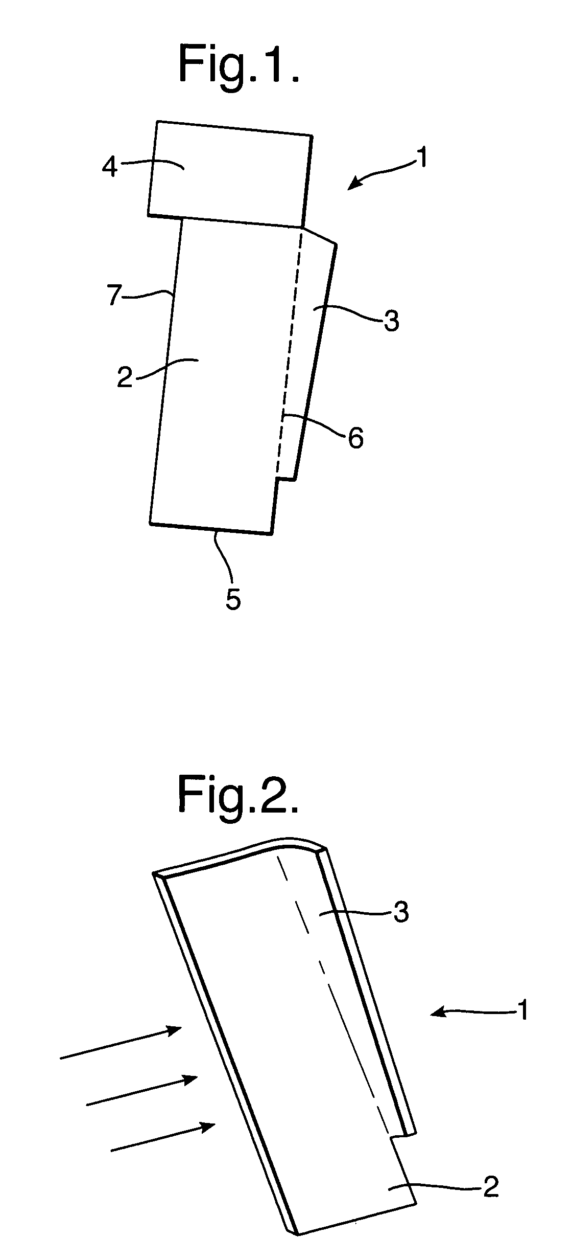
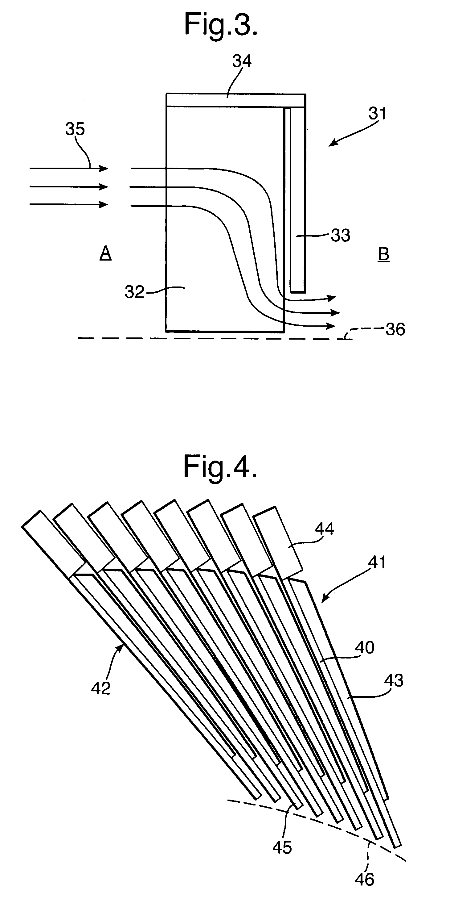
[0035]As indicated above, generally leaf seals previously have been formed to be assembled in an appropriate housing with a backing plate and a front plate in an assembly which can be cumbersome. These arrangements generally provide fixed flow apertures and pathways. In accordance with one aspect of the present invention as previously described a plurality of leaf seals are aligned axially in the direction of a potential gas flow in order to form a seal. The seal elements are profiled along at least one edge such that a fin or rib is formed which extends from a working leaf section which is generally flat and planar. As indicated, a number of these leaf elements are then associated together such that the edge profiles are adjacent to each other to define a seal ring carousel which extends between the seal elements in order to create a notional ring. As will be described later, the leaf elements, and in particular, the profile edge can be formed by stamping or crimping or etching as ...


PUM

PropertyMeasurementUnit
widthaaaaaaaaaa
strengthaaaaaaaaaa
differential pressuresaaaaaaaaaa

Abstract

In order to provide simpler manufacture and lift up and blow down control, leaf elements are provided which have profile edges arranged to associate with each other in order to create a ring carousel, either about the front or rear edge of a leaf seal arrangement. In such circumstances gas flow through the leaf seal arrangement encounters the profile edge in order to adjust leaf section position for appropriate sealing efficiency.

Description

[0001]The present invention relates to leaf seal arrangements and more particularly arrangements used in gas turbine engines.FIELD OF THE INVENTION[0002]It is known that it is necessary to provide means for sealing of gases in secondary air systems of gas turbines and other arrangements. Traditionally this has been performed using bristle type seal arrangements but more recently leaf seals have been used which comprise a leaf pack formed from a number of leaf elements held together between a front and a rear plate. The plates provide a blockage to the axial air flow while assisting the radial positioning of the leaf seal elements by turning the flow such that the leaves achieve “blow down” or “lift up” relative to the rotor in order to accommodate for eccentricities in rotation.[0003]Leaf seal arrangements have developed on and from the strength of the sealing benefits offered by brush seals in terms of a close clearance but still radially compliant seal. However, the disadvantage o...

Claims


Application Information

Patent Timeline
Patent Type & Authority Patents(United States)
IPC IPC(8): F16J15/08
CPCF16J15/3292Y10T29/49297
Inventor WILLIAMS, DAVID S
Owner ROLLS ROYCE PLC
Learn More